Optical encoder and measurement device including the same

Active Publication Date: 2019-05-02
MITUTOYO CORP
View PDF1 Cites 0 Cited by
  • Summary
  • Abstract
  • Description
  • Claims
  • Application Information

AI Technical Summary

Benefits of technology

[0041]The measurement device according to the invention includes the optical encoder according to the invention and thus, does not require a diffracted-light shielding device for blocking the noise diffracted light and can detect a uniform signal from an inte

Problems solved by technology

When signal diffracted light and noise diffracted light are incident on the light-receiving unit, the interference pattern generated from the signal diffracted light is distorted by the noise diffracted light.
As a result, the signal detected by the light-receiving unit contains noise.
There is thus a problem in that relative shift calculated from the signal by t

Method used


Image

  • Optical encoder and measurement device including the same
  • Optical encoder and measurement device including the same
  • Optical encoder and measurement device including the same

Examples


Example

[0051]A first embodiment of the invention will now be described with reference to FIGS. 1 to 3.

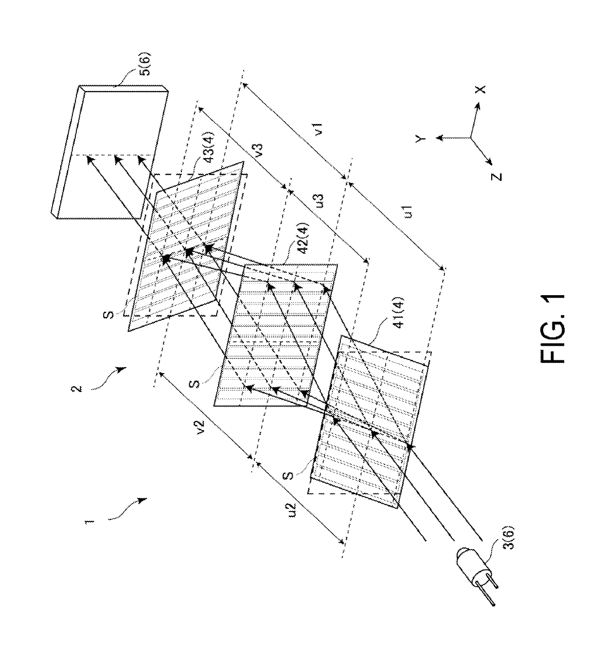
[0052]FIG. 1 is a perspective view of an optical encoder according to the first embodiment.

[0053]With reference to FIG. 1, a measurement device 1 includes an optical encoder 2. The optical encoder 2 is a linear encoder including a light source 3 configured to emit parallel light, a plurality of diffraction gratings 4 each having a grating face on which grooves S diffracting the parallel light are disposed in parallel, and a light-receiving unit 5 configured to receive the light diffracted at the diffraction gratings 4.

[0054]In the optical encoder 2, the length measurement direction is the direction in which the grooves S are disposed in parallel and orthogonal to the parallel light, and the depth direction is the direction orthogonal to the length measurement direction and the parallel light. Measurements are made along the length measurement direction.

[0055]In the following descriptions a...

Example

Second Embodiment

[0093]A second embodiment of the invention will now be described with reference to FIG. 4. Note that in the following descriptions, components that have already been described will be given the same reference signs, and descriptions thereof will be omitted.

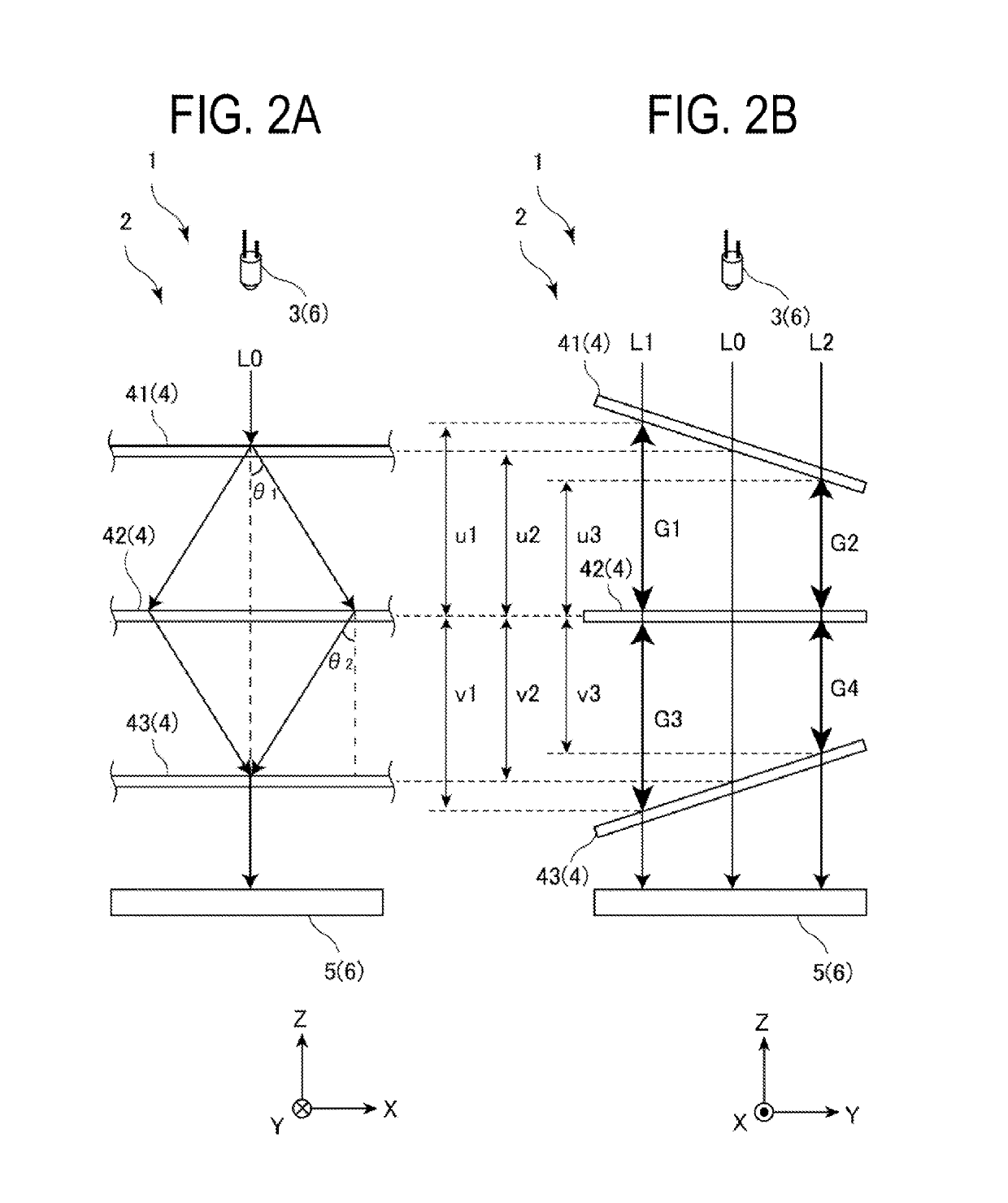
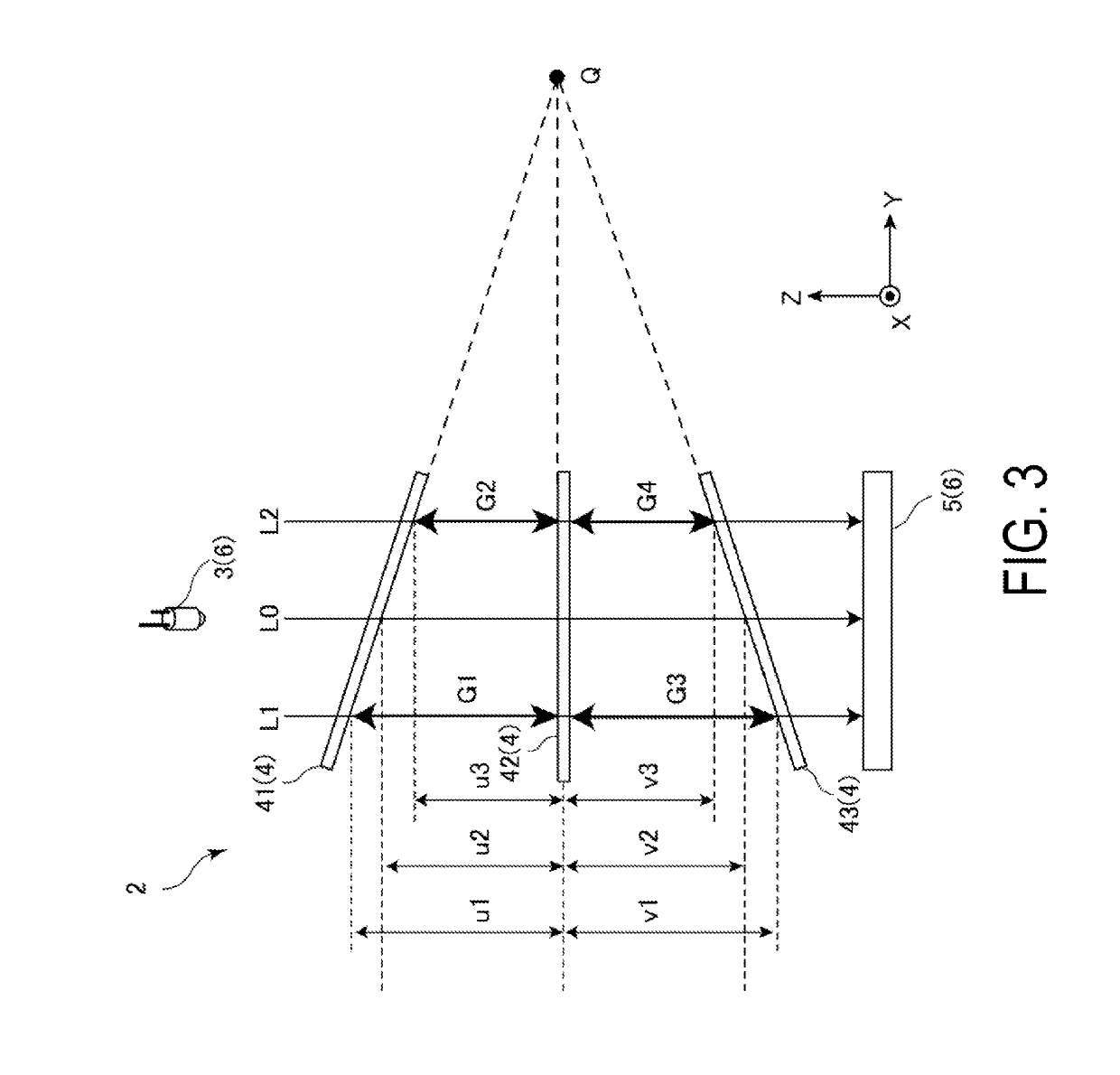
[0094]FIGS. 4A and 4B are a side view of an optical encoder according to the second embodiment in the depth direction and a side view in the length measurement direction, respectively.

[0095]The diffraction gratings 4 according to the first embodiment are formed into a planar shape and are disposed such that the planes extending from the grating faces of the diffraction gratings 4 intersect each other on a straight line. A plurality of diffraction gratings 4A of an optical encoder 2A of a measurement device 1A according to this embodiment differ from the diffraction gratings 4 according to the first embodiment in that at least two of the diffraction gratings 4A are formed into a stepwise shape and each include mult...

Example

Third Embodiment

[0101]A third embodiment of the invention will now be described with reference to FIG. 5. Note that in the following descriptions, components that have already been described will be given the same reference signs, and descriptions thereof will be omitted.

[0102]FIG. 5 is a side view of an optical encoder according to the third embodiment in the length measurement direction.

[0103]Among the diffraction gratings 4 according to the first embodiment, the first diffraction grating 41 is a first-stage diffraction grating disposed at the first stage adjacent to the light source 3, and the third diffraction grating 43 is a last-stage diffraction grating disposed at the last stage adjacent to the light-receiving unit 5. The second diffraction grating 42 is the output-stage diffraction grating of the first-stage diffraction grating (first diffraction grating 41) and the input-stage diffraction grating of the last-stage diffraction grating (third diffraction grating 43). In spec...


PUM


Abstract

An optical encoder includes a light source, a plurality of diffraction gratings including grating faces on which a plurality of grooves are disposed in parallel, and a light-receiving unit configured to receive the light diffracted at the plurality of diffraction gratings. The diffraction gratings include a first diffraction grating that is a first-stage diffraction grating adjacent to the light source, a third diffraction grating that is a last-stage diffraction grating adjacent to the light-receiving unit, and a second diffraction grating that is an output-stage diffraction grating of the first-stage diffraction grating and an input-stage diffraction grating of the last-stage diffraction grating. The diffraction gratings are disposed such that the ratio of the first gap to the third gap equals the ratio of the second gap to the fourth gap, and a length of the first gap differs from a length of the second gap.

Description

TECHNICAL FIELD[0001]The present invention relates to an optical encoder and a measurement device including the same.BACKGROUND ART[0002]An optical encoder has been known that includes a light source configured to emit parallel light, a plurality of diffraction gratings (scales) each having a grating face on which a plurality of grooves diffracting the parallel light are disposed in parallel, and a light-receiving unit (head) configured to receive the light diffracted at the diffraction gratings.[0003]In this optical encoder, the parallel light emitted from the light source is diffracted into multiple diffracted light beams at the grooves of the diffraction gratings. The diffracted light beams generate an interference pattern having the same period as that of the diffraction gratings. The light-receiving unit detects a signal from the interference pattern. The optical encoder calculates the relative shift of the scale and the head from the result (signal) detected by the light-recei...

Claims


Application Information

Patent Timeline
IPC IPC(8): G01D5/26G02B27/60G01D5/347
CPCG01D5/262G02B27/60G01D5/34746G01D5/38G02B27/4277
Inventor KIMURA, AKIHIDE
Owner MITUTOYO CORP
Why Eureka
Try Eureka