
Parison for forming blow molded medical balloon with modified portion, medical balloon, and related methods

Active Publication Date: 2015-04-16
CLEASTREAM TECH LTD
View PDF4 Cites 1 Cited by
  • Summary
  • Abstract
  • Description
  • Claims
  • Application Information

AI Technical Summary

Benefits of technology

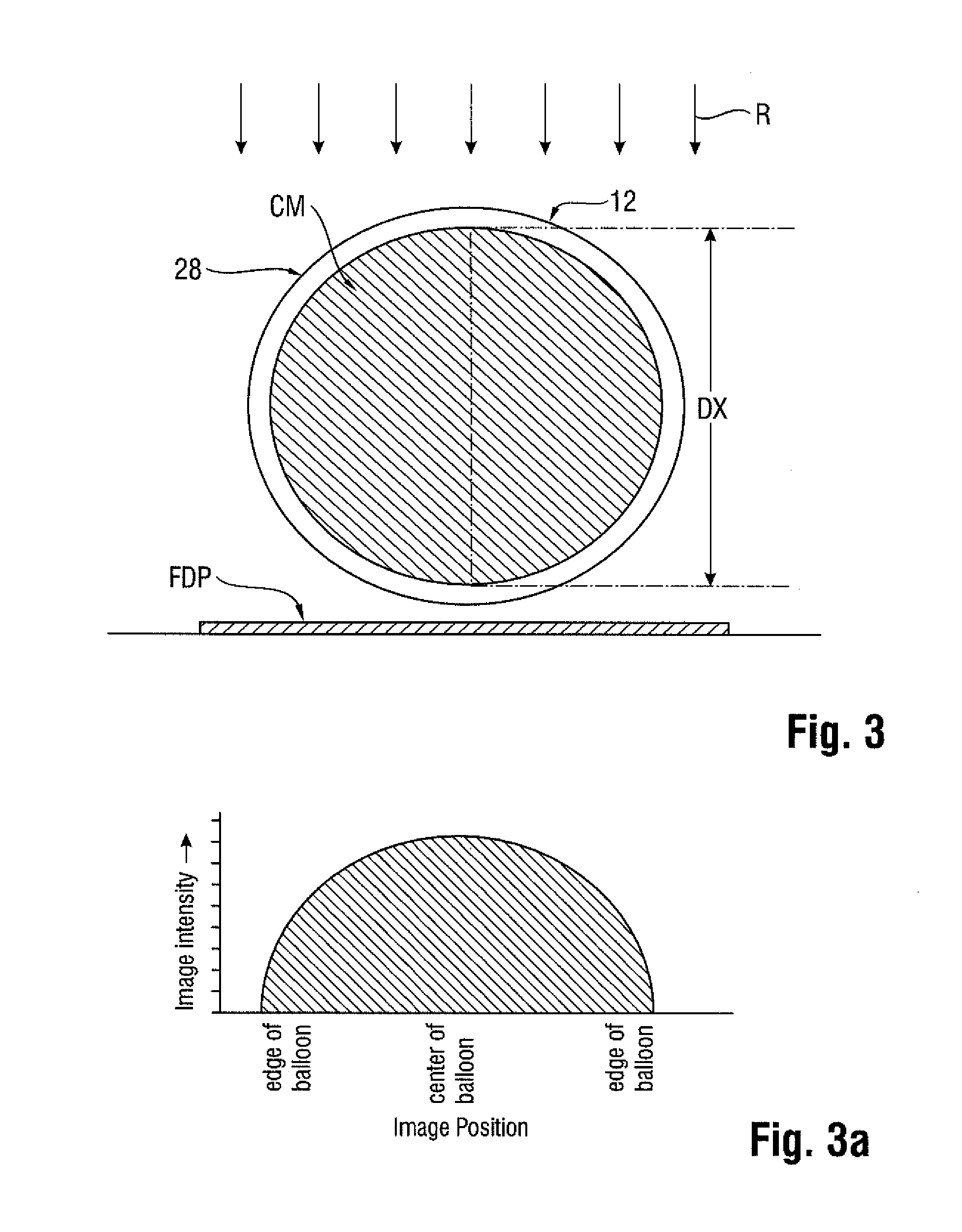
The technical effect of this patent is to improve the accuracy of identifying the working surface of a balloon during a medical procedure.

Problems solved by technology

In many clinical situations, the restrictions are caused by hard solids, such as calcified plaque, and require the use of high pressures to compact such blockages.
Commercially available balloons employ complex technology to achieve high pressure requirements without sacrificing the profile of the balloon.
The use of contrast agent prolongs the inflation / deflation times and also poses the risk of iodine exposure to patients sensitive to iodine.
In this regard, a non-radiopaque substance could be used in lieu of the contrast agent, such as for example saline or carbon dioxide, but such substances are invisible during X-ray imaging, and thus do not enhance visibility.
Even upon exercising great care to position the markers properly on the underlying shaft in alignment with anticipated boundaries of the working surface when the balloon is inflated, there remains a tendency for mismatch clue to several possible factors.
The balloon also has a tendency to grow in the longitudinal direction when inflated, especially with large and particularly long balloons.
This may lead to misalignment between radiopaque markers fixed to the shaft and the working surface.
Whatever the cause, the resulting misalignment may prevent the clinician from accurately identifying the location of the working surface of the balloon during an interventional procedure.
This can give the clinician the false perception that the balloon remains inflated, when in fact it is not.

Method used


Image

  • Parison for forming blow molded medical balloon with modified portion, medical balloon, and related methods
  • Parison for forming blow molded medical balloon with modified portion, medical balloon, and related methods
  • Parison for forming blow molded medical balloon with modified portion, medical balloon, and related methods

Examples


Embodiment Construction

[0023]The description provided below and in regard to the figures applies to all embodiments unless noted otherwise, and features common to each embodiment are similarly shown and numbered.

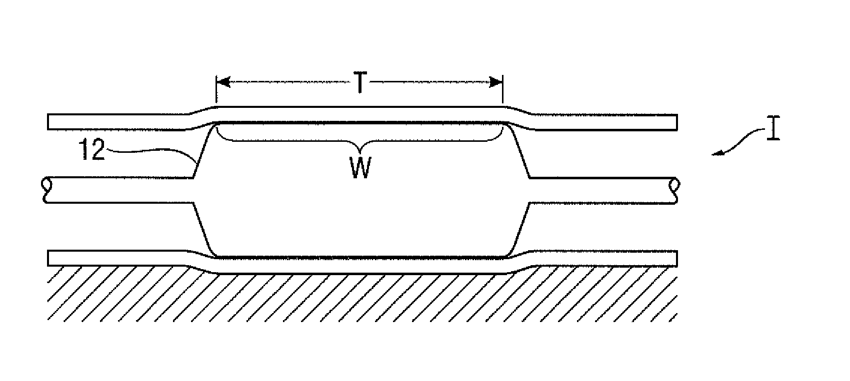
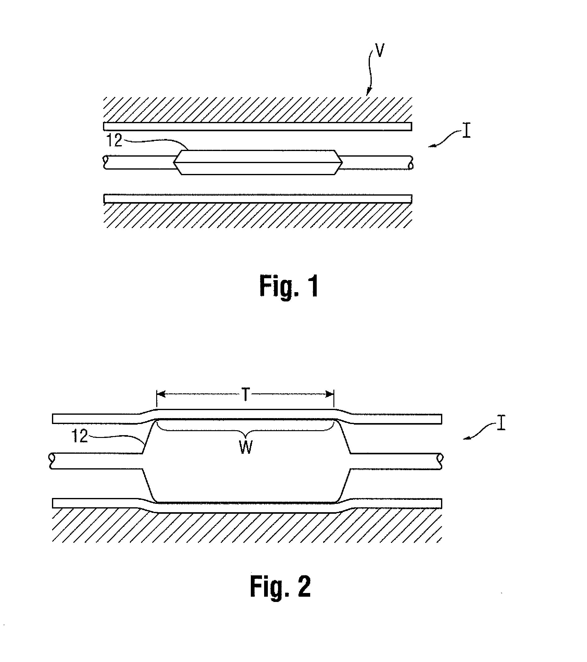
[0024]Provided is a catheter 10 having a distal portion 11 with a balloon 12 mounted on a catheter tube 14. Referring to FIGS. 6, 7, and 8, the balloon 12 has an intermediate section 16, or “barrel,” and end sections 18, 20. In one embodiment, the end sections 18, 20 reduce in diameter to join the intermediate section 16 to the catheter tube 14 (and thus sections 18, 20 are generally termed cones or cone sections). The balloon 12 is sealed at balloon ends (proximal end 15a and distal end 15b) on the cone sections 18, 20 to allow the inflation of the balloon 12 via one or more inflation lumens 17 extending within catheter tube 14 and communicating with the interior of the balloon 12.

[0025]The catheter tube 14 also includes an elongated, tubular shaft 24 forming a guidewire lumen 23 that directs the...


PUM

PropertyMeasurementUnit
Circumferenceaaaaaaaaaa
Radiopacityaaaaaaaaaa

Abstract

A parison for being blow molded into a medical balloon for a catheter includes a first tubular layer having a functional modification and a second tubular layer adapted for bonding with the first tubular layer to form the blow molded balloon. Related methods are also disclosed.

Description

[0001]The following U.S. patent applications are incorporated by reference: 61 / 608,852; 61 / 608,859; 61 / 608,862; 61 / 608,897; 61 / 608,902; 61 / 608,908; 61 / 608,913; 61 / 608,917; 61 / 608,927; 61 / 608,932; 61 / 608,941; and 61 / 747,444.TECHNICAL FIELD[0002]This disclosure relates generally to balloons for performing medical procedures, such as angioplasty and, more particularly, to a parison for forming a blow molded medical balloon having a modified portion, such as a layer that is radiopaque, a medical balloon, and related methods.BACKGROUND OF THE INVENTION[0003]Balloons are routinely used to resolve or address flow restrictions or perhaps even complete blockages in tubular areas of the body, such as arteries or veins. In many clinical situations, the restrictions are caused by hard solids, such as calcified plaque, and require the use of high pressures to compact such blockages. Commercially available balloons employ complex technology to achieve high pressure requirements without sacrificin...

Claims


Application Information

Patent Timeline
IPC IPC(8): A61M25/10B29C49/22
CPCA61M25/1029A61M25/10B29C49/22A61M2025/1031A61M2025/1075A61M2025/1079B29L2031/753A61M25/1027B29L2031/7543B29C2049/222A61M2025/1086B29D22/02B29C49/0005A61L29/18B32B2535/00
Inventor FILLMORE, PAUL ANDERSRONAN, ALLANRYAN, EOINSCHAFFER, ANDREW
Owner CLEASTREAM TECH LTD
Learn More