
Mixer

a technology of mixer and mixer, which is applied in the field of mixer, can solve the problems of engine backfire, etc., and achieve the effects of preventing backfire flames, simple arrangement, and extinguishing backfire flames

Inactive Publication Date: 2007-06-21
IWAI TRADING
View PDF6 Cites 3 Cited by
  • Summary
  • Abstract
  • Description
  • Claims
  • Application Information

AI Technical Summary

Benefits of technology

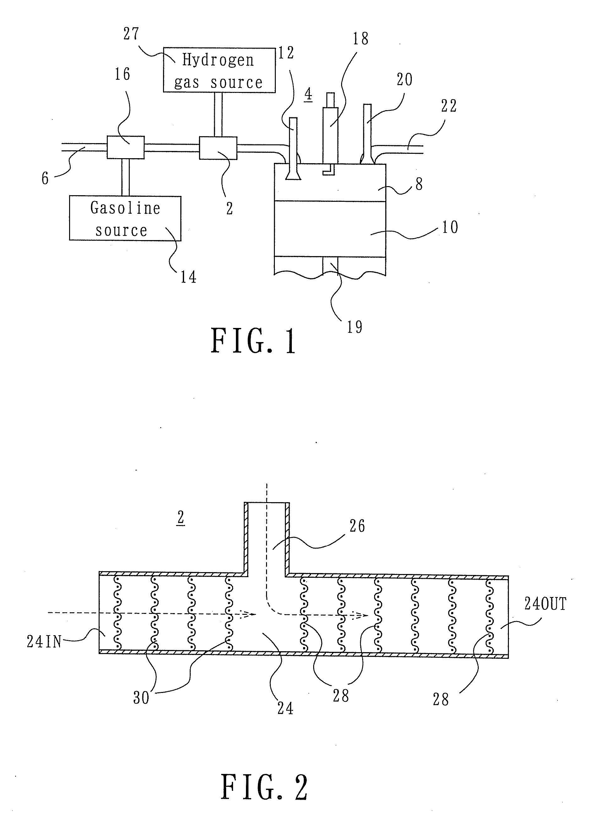
[0006] With the above-described arrangement, when an inlet valve of the engine is opened, the gaseous fuel, which inherently is hard to mix with air because of its different specific gravity than air, can be stirred and mixed well with air when they pass through the first net by virtue of what is called Karma vortices in hydromechanics before being supplied to the engine. Like this, the gaseous fuel and air can be mixed well with a very simple arrangement.
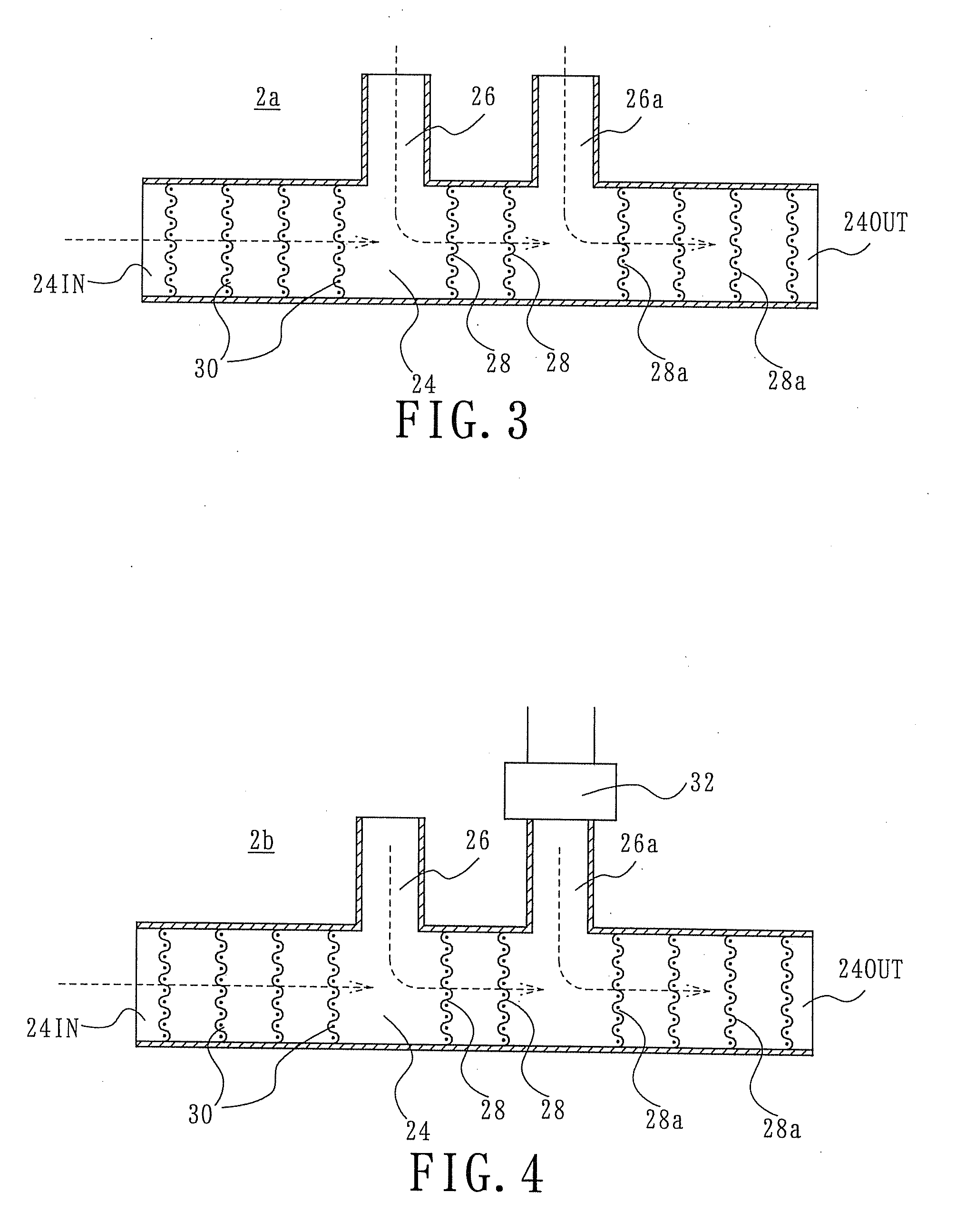
[0015] With this arrangement, better mixing of the gaseous fuel and the gasified liquid fuel, or the gaseous fuel, the gasified liquid fuel and the combustion promoting gas can be realized.

Problems solved by technology

It is known that when gas is combusted in a reciprocating engine, the engine tends to backfire.

Method used


Image

  • Mixer
  • Mixer
  • Mixer

Examples


Embodiment Construction

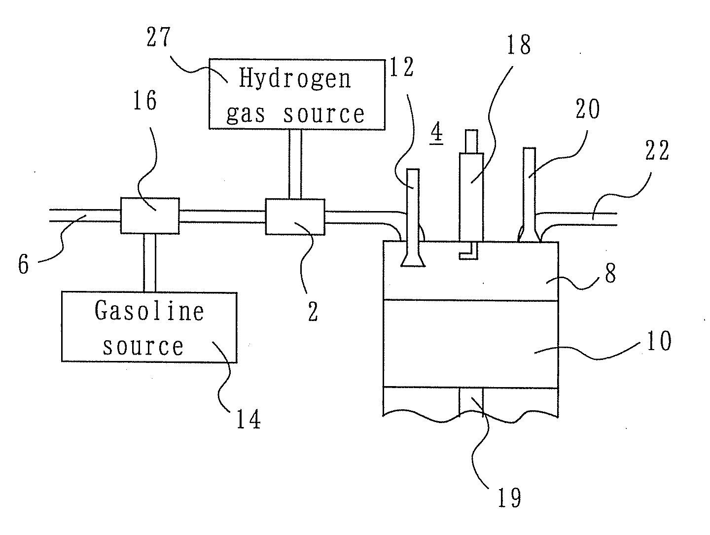
[0022] A mixer 2 according to a first embodiment of the invention is disposed in an intermediate portion of an intake tube 6 for supplying air to, for example, a reciprocating engine 4, as shown in FIG. 1. The reciprocating engine 4 includes a piston in a cylinder 8. In the reciprocating engine 4, when the piston 10 goes down, an inlet valve 12 opens, and gasoline from a gasoline source 14 and air flowing through the intake tube 6 are mixed in a carburetor 16 disposed at an intermediate location of the intake tube 6. The mixture is then sucked into the cylinder 8, and the inlet valve is closed. Then, the piston 10 starts moving upward to compress the mixture gas, and, when the mixture gas is sufficiently compressed, an ignition plug 18 ignites the mixture gas to cause instantaneous combustion of the mixture gas. High pressure caused by the combustion drives down the piston 10 with strong force. This strong force makes a crank shaft (not shown) connected to the piston 10 by means of ...


PUM

PropertyMeasurementUnit
pressureaaaaaaaaaa
specific gravityaaaaaaaaaa
areaaaaaaaaaaa

Abstract

A path (24) is formed in an intake tube (6), which supplies external air to a reciprocating engine (4). External air flowing from an inlet port to an outlet port of the path (24). A gaseous fuel path (26) is connected to the path (24) at an intermediate location thereof. A gaseous fuel, lighter than air, is supplied through the gaseous fuel path (26) into the path (24). A plurality of nets (8) are disposed in an area of the path (24) between the outlet port and the gaseous fuel path (26). The nets (28) are spaced along the length of the path (24) with the outer peripheral surface of each net (28) being in contact with the inner surface of the path (24).

Description

[0001] This invention relates to a mixer for mixing a gas with air and supplying the mixture to an engine having a piston. BACKGROUND OF THE INVENTION [0002] In an engine which generate power by burning a gaseous fuel, e.g. Hydrogen gas, the gaseous fuel is mixed with air before being supplied to the engine. It is necessary to mix the hydrogen gas with air with a high efficiency, and, a technique to realize it is disclosed in, for example, JP 2002-81346 A. According to the technique disclosed in this Japanese patent publication, interior paths and exterior paths are circumferentially formed in an air turbo ram engine. The interior and exterior paths alternate with each other. Air compressed by a fan is blown through the respective exterior paths, and hydrogen gas is blown through the respective interior paths, whereby the air and hydrogen gas are mixed with each other. A guide vane is provided in order to forcibly direct the hydrogen gas in each interior path to flow outward, and th...

Claims


Application Information

Patent Timeline
Patent Type & Authority Applications(United States)
IPC IPC(8): F02B43/00F02M29/00
CPCB01F3/02B01F5/0682B01F5/0693Y02T10/36Y02T10/32F02M29/04F02D19/0644F02M21/04Y02T10/30B01F23/10B01F25/4523B01F25/45
Inventor IWAI, YOSHIRO
Owner IWAI TRADING
Learn More