Exhaust muffler

Active Publication Date: 2008-06-12
DOLMAR
View PDF17 Cites 0 Cited by
  • Summary
  • Abstract
  • Description
  • Claims
  • Application Information

AI Technical Summary

Benefits of technology

[0008]It is the object of the invention to provide an exhaust muffler in which the temperature of the exhaust gas is reduced substantially in the area of the outlet int

Problems solved by technology

In this case, it is unimportant whether part of the lengthening

Method used


Image

  • Exhaust muffler
  • Exhaust muffler
  • Exhaust muffler

Examples


Embodiment Construction

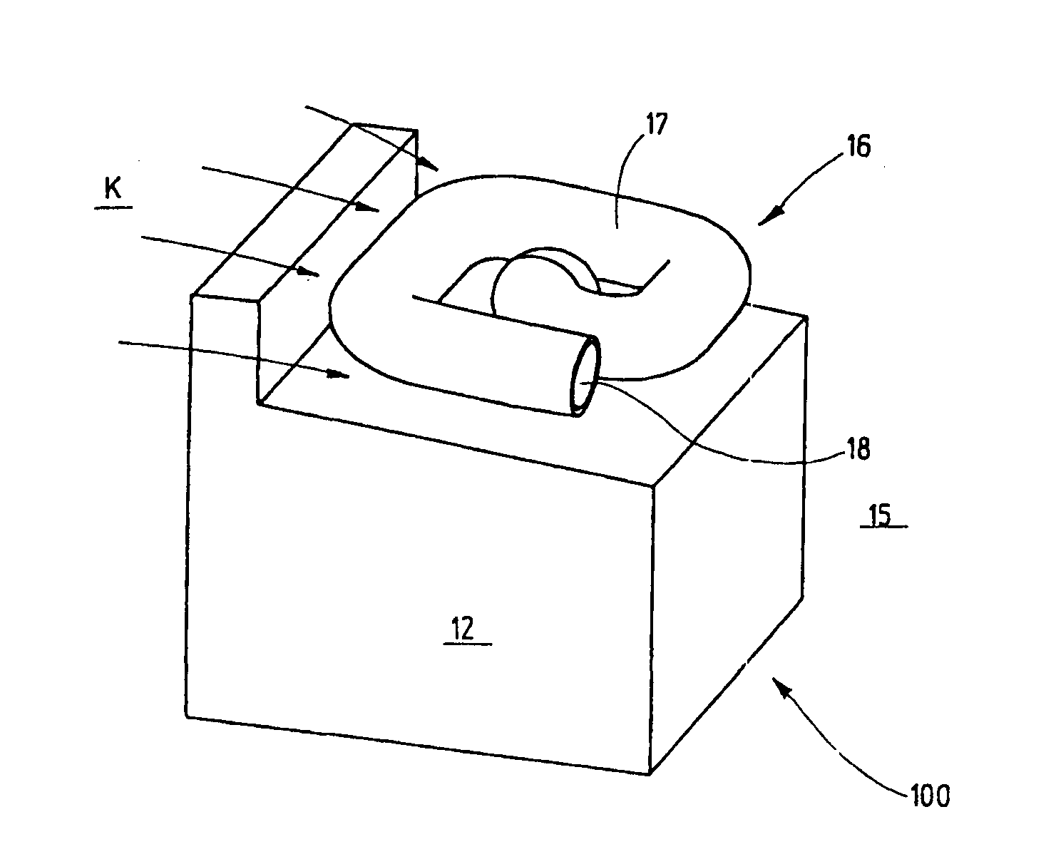
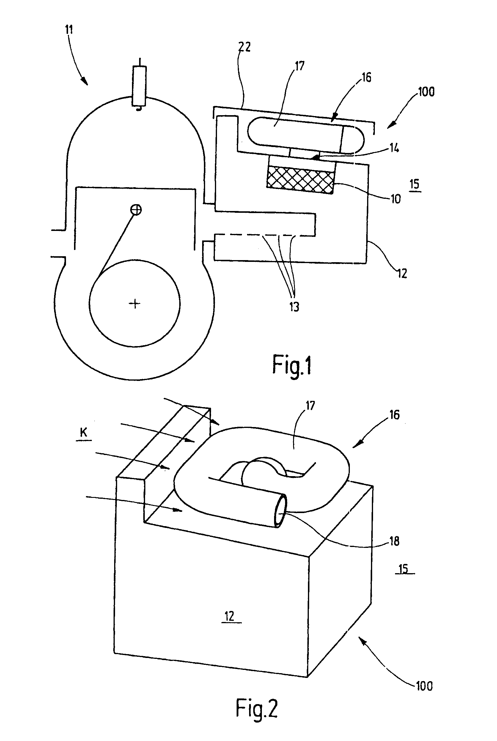
[0032]FIG. 1 shows an exhaust muffler 100 with an internal combustion engine 11, which is a component of a hand-held tool which however is not shown, as an example. The tool can for example be a motor-driven chain saw, a disk grinder or the like. The exhaust muffler 100 has a housing 12 in which a catalyst 10 is arranged. Furthermore, the housing 12 is constructed with a plurality of inlet openings 13 through which exhaust gas is passed from the motor 11 into the exhaust muffler 100. The exhaust gas enters the housing 12 at a temperature of around 600 oC. Inside the housing 12 the catalyst 10 converts the hydrocarbons contained in the exhaust gas large into carbon dioxide and water. The chemical conversion process involves an exothermic reaction process wherein the around 600 oC hot exhaust gas from the motor 11 can be further heated to temperatures above 1000 oC in the housing 12.

[0033]The housing 12 is further constructed with an outlet opening 14 through which the exhaust gas is ...


PUM


Abstract

In order to provide an exhaust muffler for an internal combustion engine, especially a portable implement, comprising a catalyst which is arranged in a housing which has at least one inlet opening and one outlet opening for exhaust gas flowing out from the internal combustion engine into the environment, in which the temperature of the exhaust gas in the area of the outlet into the environment is reduced substantially and/or a sufficiently long path length is made available so that flame development can be avoided especially in the outlet area of the exhaust muffler, it is proposed that the outlet opening has at least one means through which exhaust gas flows, which is arranged partially outside the housing and has an outlet facing the environment, whereby the flow path of the exhaust gas in the direction of the environment is lengthened.

Description

BACKGROUND OF THE INVENTION[0001]The invention relates to an exhaust muffler for an internal combustion engine, especially of a portable implement, comprising a catalyst which is arranged in a housing, which has at least one inlet opening and one outlet opening for an exhaust gas flowing from an internal combustion engine into an environment.[0002]The exhaust gases from internal combustion engines generally enter the catalyst at an exhaust gas temperature of about 600 oC. A chemical conversion of the exhaust gases takes place inside the catalyst. In this case, three processes take place simultaneously adjacent to one another: NOx is reduced to nitrogen, releasing oxygen, CO is oxidized to CO2 and HC compounds are oxidized to CO2 and H2O, consuming oxygen at the same time. As a result of the chemical conversion processes, the temperature of exhaust gas “converted” by the catalyst is increased to about 1000 oC. When this heated exhaust gas emerges from the catalyst, there is a risk of...

Claims


Application Information

Patent Timeline
IPC IPC(8): F01N1/12F01N1/02F01N3/02F01N13/00F01N13/08
CPCF01N3/02F01N13/002Y02T10/20F01N2230/04F01N2590/06F01N13/082Y02T10/12
Inventor GORENFLO, ERNST
Owner DOLMAR
Why Eureka
Try Eureka