
Method of increasing power within an optical cavity with long path lengths

a technology of optical cavity and path length, applied in the field of cavity-enhanced absorption spectroscopy instruments, can solve the problems of reducing the utility of icos instruments, increasing the cost, and limiting the sensitivity of instruments, so as to increase the power injected into the cavity, the effect of long path length and high nois

Active Publication Date: 2018-02-15
ABB INC
View PDF0 Cites 7 Cited by
  • Summary
  • Abstract
  • Description
  • Claims
  • Application Information

AI Technical Summary

Benefits of technology

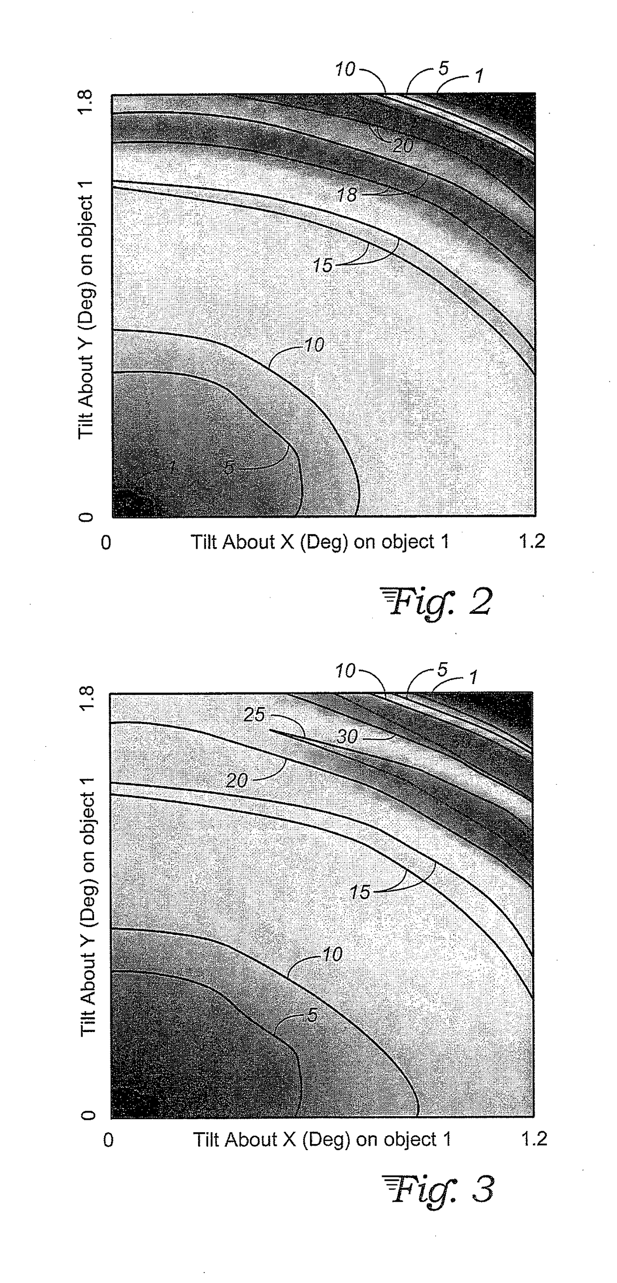
The present invention introduces a method for increasing the power injected into a cavity while retaining long path lengths. This is achieved by using a hole or reduced reflectivity area of the input mirror, which allows for a much higher proportion of light than usual for ICOS or other CEAS methods. An astigmatic cavity configuration is used to prevent the beam from exiting the cavity after only a few reflections. The method also reduces the light intensity at the detector, but significantly simplifies alignment and allows us to use a wide range of alignments and mirror configurations. The number of passes may be enhanced by embodiments having the light beam directed through the aperture at a tilt angle greater than 0.5° and selected to maximize the number of passes, and in some embodiments, the aperture could be located off of a central axis of the cavity, i.e. off-axis injection of the light beam.

Problems solved by technology

The low power transmission limits instrument sensitivity and requires high power lasers and / or high gain amplifier detectors—all of which increase the cost and decrease the utility of ICOS instruments.
Of note, lasers operating between 3 and 4 um produce limited power, making it difficult to accurately and precisely measure the many important hydrocarbon absorptions in the region.
Also, high reflectivity mirrors made to operate at wavelengths longer than about 8 um require materials in the Bragg stack that have high optical losses—the many cavity reflections that are a requirement of cavity-enhanced absorption spectroscopy (CEAS) rob the system of light, resulting in very small powers incident on the detector.
These previously proposed embodiments succeed in increasing the transmitted power, but sacrifice path length as a result, yielding mere tens of reflections instead of the thousands common to standard CEAS.
This is a result of limitations on spherical-spherical and planar-planar cavities that was recognized almost immediately after the introduction of multi-pass cells.
This limits the cavity configurations to those that have a reentrant condition, i.e., passing in and out of the same hole and makes them hard to align and operate under field conditions (vibrations, changing temperature and pressure, etc.).

Method used


Image

  • Method of increasing power within an optical cavity with long path lengths
  • Method of increasing power within an optical cavity with long path lengths
  • Method of increasing power within an optical cavity with long path lengths

Examples


Embodiment Construction

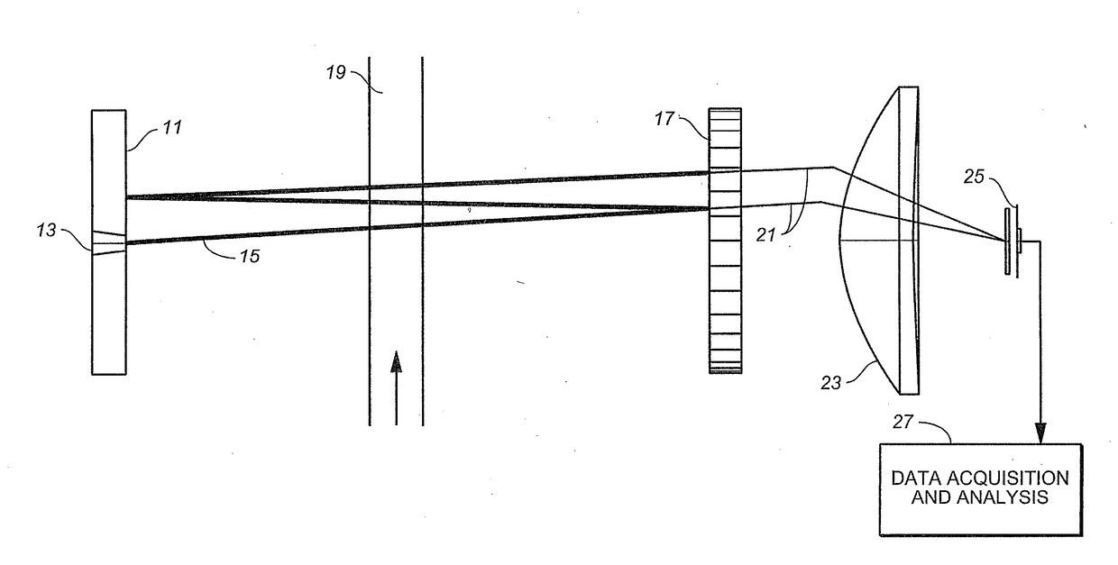
[0020]With reference to FIG. 1, our invention utilizes an astigmatic cavity configuration similar to an astigmatic Herriott cell to prevent the beam from exiting the cavity after a few reflections. A first mirror 11 has an injection hole 13 so that the mirror 11 serves as an injection mirror for the optical cavity. A light source (not shown) is located outside of the cavity and provides a light beam 15 that is directed through the injection hole 13 into the cavity. A second mirror 17 spaced apart from the injection mirror 11 is partially transmissive of the light beam 15. The light beam 15 makes multiple round trips within the cavity and passes through a sample volume 19 some minimum number of times so as to be subject to absorption by any gaseous or vapor sample within the sample volume 19. Light 21 transmitted partially through the mirror 17 is collected, for example by a lens 23, so as to impinge upon and be detected by a detector 25.

[0021]The signal output from detector 25 is co...


PUM

PropertyMeasurementUnit
reflectivityaaaaaaaaaa
tilt angleaaaaaaaaaa

Abstract

A cavity-enhanced absorption spectroscopy instrument has an optical cavity with two or more cavity mirrors, one mirror of which having a hole or other aperture for injecting a light beam, and the same or another mirror of which being partially transmissive to allow exit of light to a detector. A spherical-spherical configuration with at least one astigmatic mirror or a spherical-cylindrical configuration where the spherical mirror could also be astigmatic prevents a reentrant condition wherein the injected beam would prematurely exit the cavity through the aperture. This combination substantially increases the number of passes of the injected beam through a sample volume for sensitive detection of chemical species even in less than ideal conditions including low power laser or LED sources, poor mirror reflectivity or detector noise at the wavelengths of interest, or cavity alignment issues such as vibration or temperature and pressure changes.

Description

STATEMENT REGARDING FEDERALLY-SPONSORED RESEARCH AND DEVELOPMENT[0001]This invention was made with government support under SBIR contract number DE-SC0007654, awarded by the Department of Energy. The government has certain rights in the invention.TECHNICAL FIELD[0002]The present invention relates to cavity-enhanced absorption spectroscopy instruments, such as integrated cavity output spectroscopy systems or cavity ringdown systems, and in particular relates to optical cavity features of such devices that provide long effective path lengths.BACKGROUND ART[0003]Integrated cavity output spectroscopy (ICOS) is used to measure small optical absorptions for the quantification and speciation of trace constituents. ICOS uses two or more high reflectivity mirrors to trap light and increase the effective path length. In ICOS, the light passes through the front mirror to enter the cavity and through (usually) another mirror, such as the back mirror, onto the detector. This double transmission ...

Claims


Application Information

Patent Timeline
Patent Type & Authority Applications(United States)
IPC IPC(8): G01J3/02G01N21/3504G01J3/42
CPCG01J3/021G01N2201/06113G01N21/3504G01J3/42G01J3/0291G01J3/0208G01J3/0243G01J3/0286G01N21/39G01N2021/391G01N2021/399
Inventor LEEN, JOHN BRIANBRAMALL, NATHAN E.
Owner ABB INC
Learn More