Mirror pulse compressor for electron beam apparatus

Active Publication Date: 2016-08-02
ELECTRON OPTICA
View PDF3 Cites 3 Cited by
  • Summary
  • Abstract
  • Description
  • Claims
  • Application Information

AI Technical Summary

Benefits of technology

The patent describes an apparatus for compressing an electron pulse. The apparatus uses a laser to create a beam of photons that illuminates an electron beam source. The electron beam enters a device that splits it into two parts, with the higher energy electrons forming the leading edge of the pulse and the lower energy electrons forming the trailing edge. The electron beam is then focused using an electron lens. The higher energy electrons penetrate more deeply into a retarding field, resulting in a longer path length in the device. The lower energy electrons penetrate less deeply, resulting in a shorter path length. After reflection, the lower energy electrons exit the device before the higher energy electrons. The apparatus causes the electron pulse to be deflected and reenters the beam separator, where it is redirected back into the optical axis. The electrons are then scattered by the specimen and used to create an image or diffraction pattern of the specimen. The technical effect of this invention is the creation of a device that can compress an electron pulse, resulting in a higher resolution image or diffraction pattern of a specimen.

Problems solved by technology

The observation of dynamical processes in conventional electron microscopes is limited by the frame acquisition rate, which is typically on the order of milliseconds to seconds.
Pulsed laser techniques have the requisite temporal resolution, but not the spatial resolution to follow these processes.
Unfortunately, electron-electron interactions broaden the pulse as they travel from the photocathode to the sample, resulting in a loss of temporal resolution when the pulse arrives at the specimen.
However, electrons with such high kinetic energies not only have low scattering cross-sections yielding weak contrast, they also inevitably cause radiation damage on most types of specimens.
Although RF methods have great potential, they lack the technical simplicity of static electron optics.
Furthermore, synchronization of the RF cavity with the pulsed laser can be a challenge.
Although the incident and exiting electron paths are parallel, they do not coincide due to an out of-plane offset between the magnets in the first and the second half of the deflection, which makes alignment and beam set up challenging.
Furthermore, the deflectors introduce significant and unavoidable aberrations.
However, the symmetry invoked by the electrostatic capacitor also compresses the pulse at the deflector midplane, after a 180° deflection, which is likely to result in significant Coulomb repulsion effects.
The skewed entry complicates the overall column alignment, as there is no direct line of sight from the electron source to the specimen.
In addition, the large entrance angle introduces significant aberrations and a significant tilt of the pulse front, which complicates the experimental setup.

Method used


Image

  • Mirror pulse compressor for electron beam apparatus
  • Mirror pulse compressor for electron beam apparatus
  • Mirror pulse compressor for electron beam apparatus

Examples


Embodiment Construction

Electron Mirror-Based Pulse Compressor

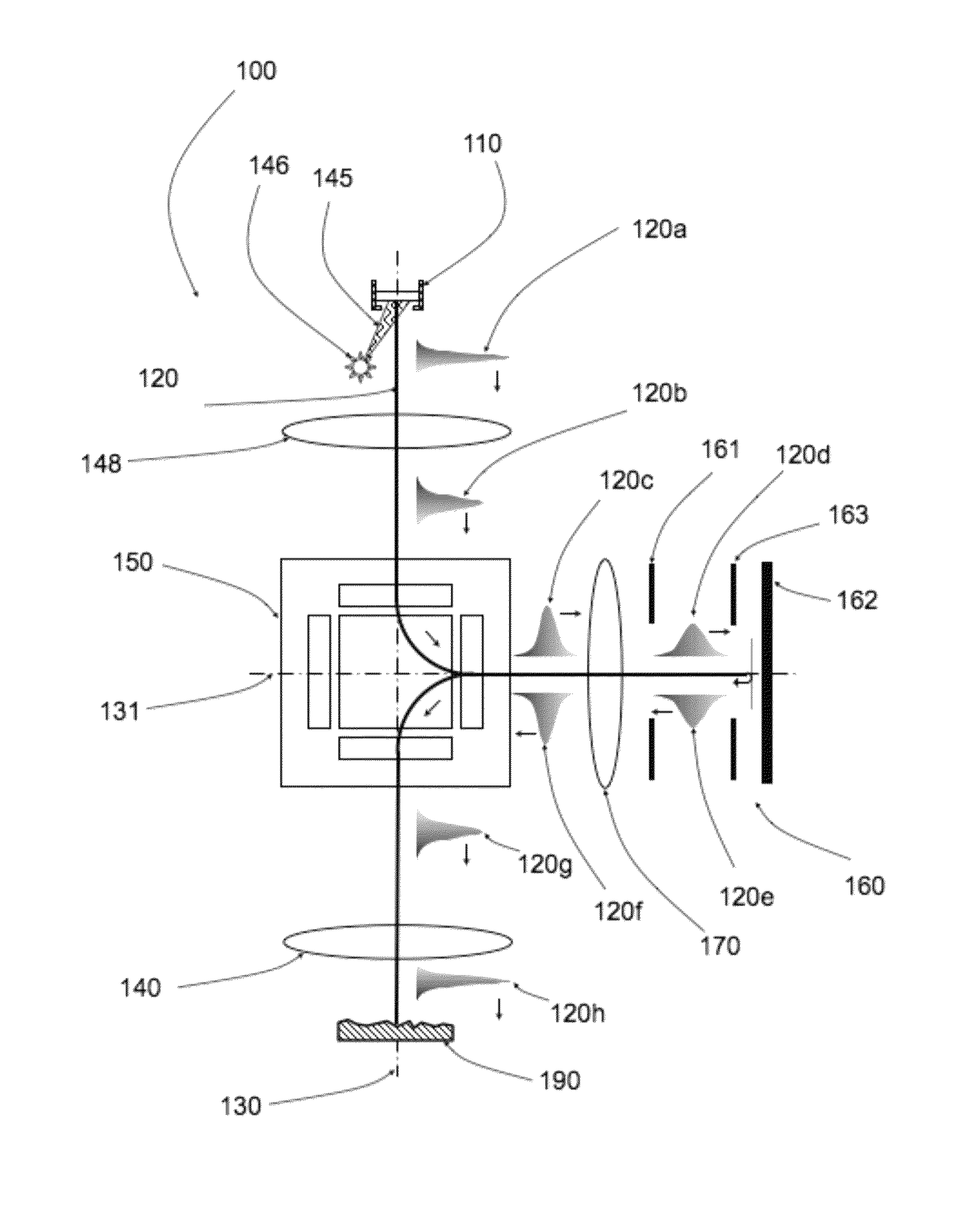
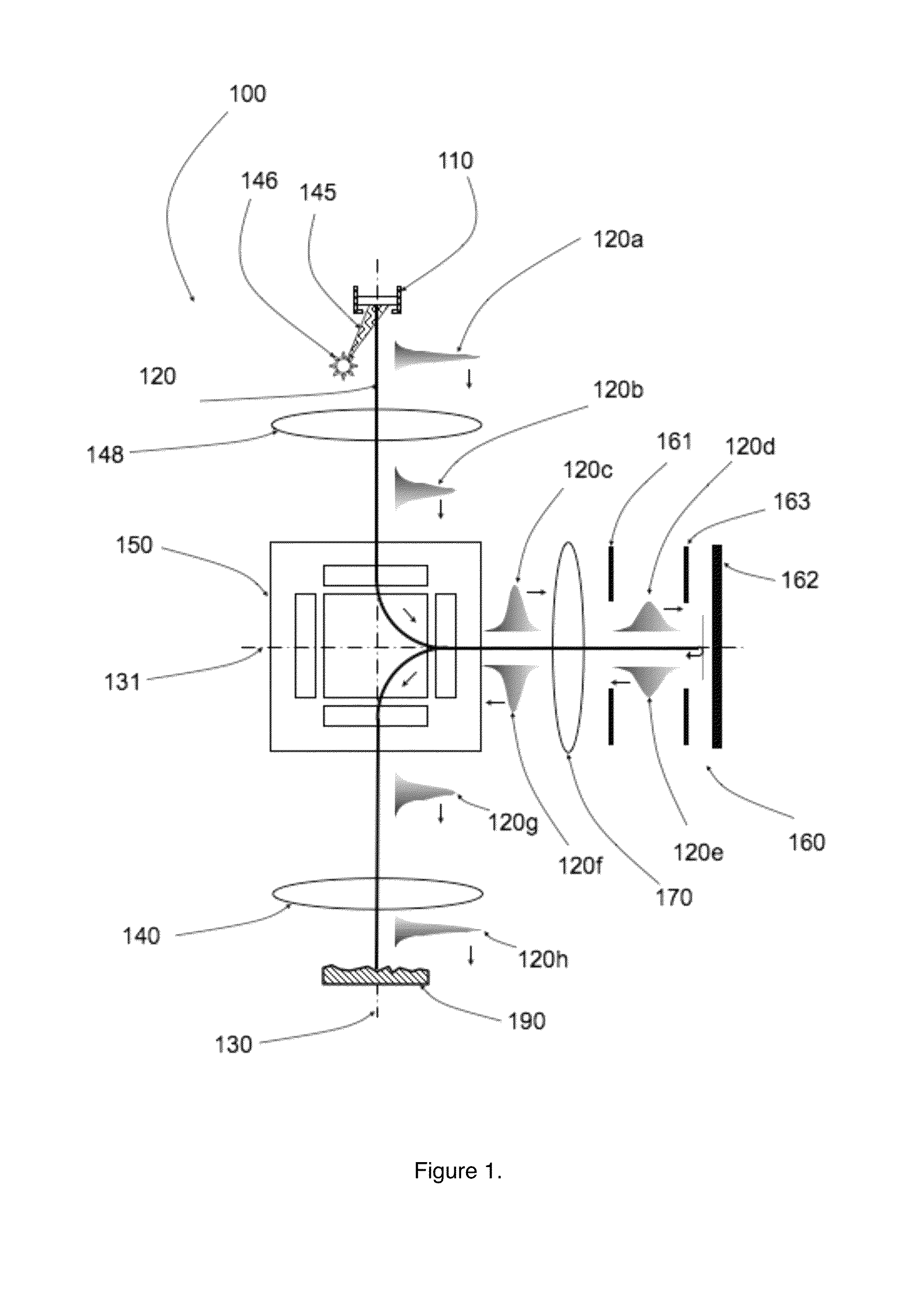
[0021]FIG. 1 is a diagram depicting a structure for an electron beam apparatus 100 comprising a magnetic prism separator and an electron mirror that are configured as an electron pulse compressor. In this apparatus 100, an electron emitter 110 generates an ultrashort pulse of primary electrons 120a along the vertical optical axis 130 defined by the objective lens 140. The duration of an ultrafast pulse is typically less than 1 picosecond. In one implementation, the electron emitter 110 is a photocathode and the ultrafast pulse of electrons is generated by illuminating the photocathode with photons 145 generated by a pulsed laser 146. One or more condenser lenses 148 collimate the primary electron pulse into the magnetic prism separator 150, a deflection element composed of an array of uniform magnetic fields of different length and strength so as to provide a mechanism for simultaneous deflection and stigmatic focusing. An optimized prism separa...


PUM


Abstract

One embodiment pertains to an apparatus for compressing an electron pulse. An electron source is illuminated by a pulsed laser and generates a pulse of electrons. The pulse enters a beam separator which deflects the electrons by 90 degrees into an electron mirror. The faster, higher energy electrons form the leading edge of the pulse and penetrate more deeply into the retarding field of the electron mirror than the lower energy electrons. After reflection, the lower energy electrons exit the electron mirror before the higher energy electrons and form the leading edge of the pulse. The reflected pulse reenters the separator and is deflected by 90 degrees towards the specimen. The fast, higher energy electrons catch up with the slow, low energy electrons as the electrons strike the specimen. The electrons are scattered by the specimen and used to form a two-dimensional image or diffraction pattern of the specimen.

Description

BACKGROUND OF THE INVENTION[0001]1. Field of the Invention[0002]The present invention relates generally to charged particle beam apparatus, and more specifically to electron microscopy and electron diffraction methods for high spatial resolution observation of ultrafast dynamical processes on the femtosecond scale.[0003]2. Description of the Background Art[0004]Optical microscopes, the simplest and most common instruments used to image objects too small for the naked eye to see, uses photons with visible wavelengths for imaging. The specimen is illuminated with a broad light beam, and a magnified image of the specimen can be observed using an eye piece or camera. The maximum magnification of a light microscope can be more than 1000× with a diffraction-limited resolution limit of a few hundred nanometers. Improved spatial resolution in an optical microscope can be achieved when shorter wavelengths of light, such as the ultraviolet, are utilized for imaging.[0005]An electron microscop...

Claims


Application Information

Patent Timeline
IPC IPC(8): G21K5/04H01J37/14H01J37/285H01J37/28H01J37/20H01J37/147
CPCH01J37/1471H01J37/285H01J37/28H01J37/20H01J37/14H01J2237/1523H01J2237/2802G01R31/307H01J37/045H01J37/153H01J2237/0432H01J2237/06333H01J2237/065H01J2237/1534H01J2237/2803G01R31/44
Inventor MANKOS, MARIAN
Owner ELECTRON OPTICA
Why Eureka
Try Eureka