

Piezoelectric Oscillator Part
- Summary
- Abstract
- Description
- Claims
- Application Information
AI Technical Summary
Benefits of technology
Problems solved by technology
Method used
Image

Examples
first embodiment
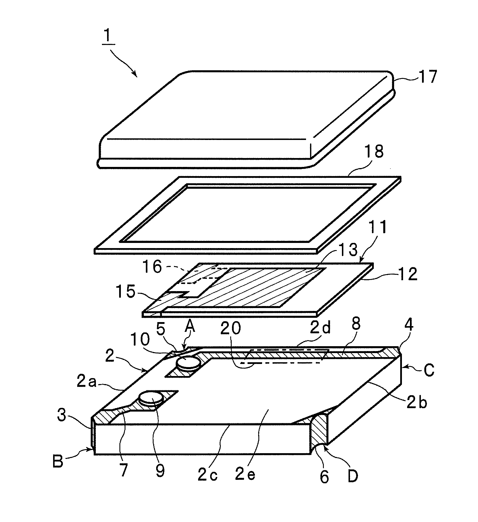
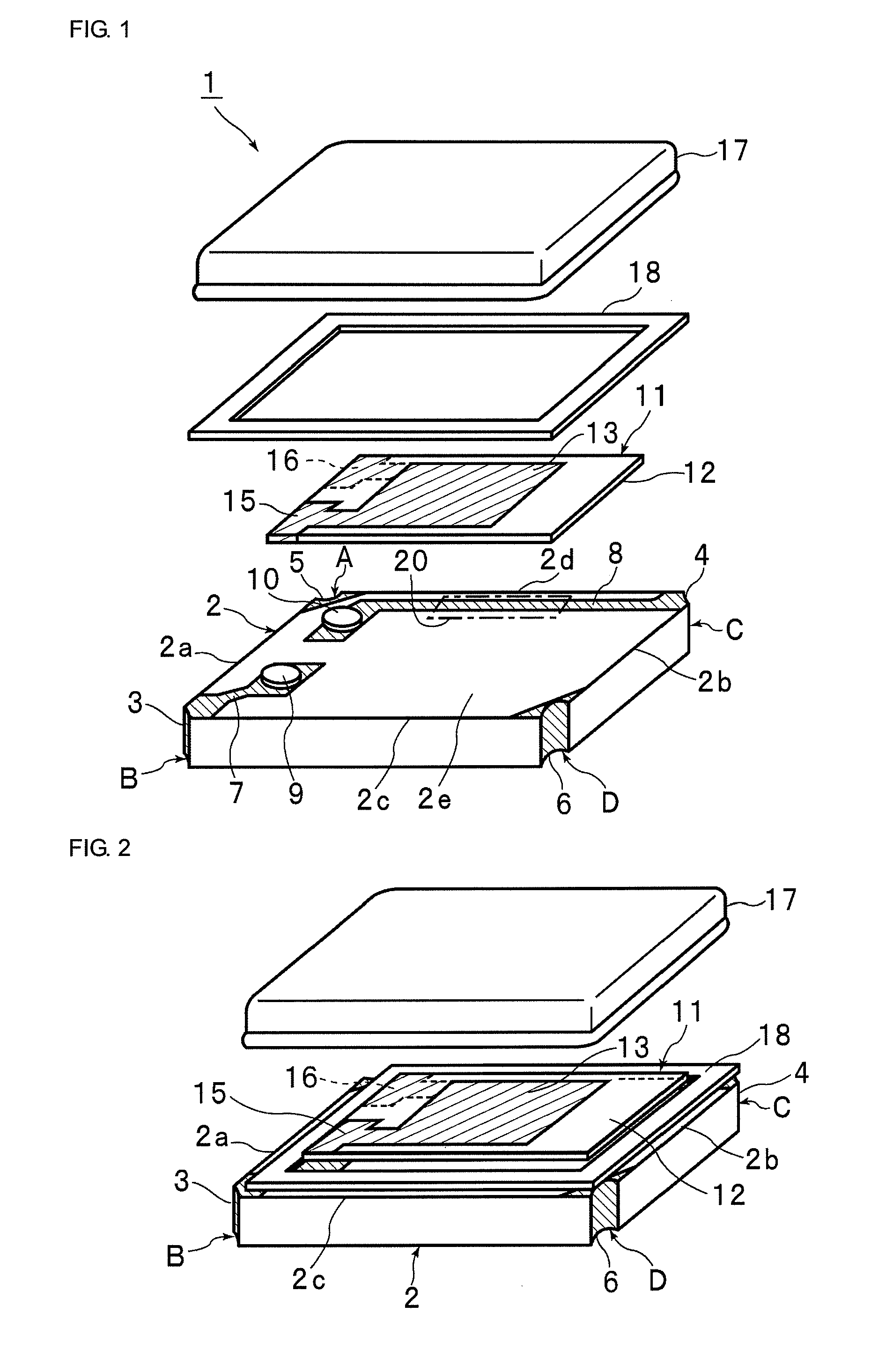
[0064]FIG. 1 is an exploded perspective view of a piezoelectric oscillator part according to the present invention, and FIG. 2 is a perspective view for illustrating the process of combining the piezoelectric oscillator part with a cap thereof.
[0065]A piezoelectric oscillator part 1 includes a case substrate 2 having the shape of an approximately rectangular plane. The rectangular-shaped plane has first and second short sides 2a and 2b facing each other, and first and second long sides 2c and 2d facing each other. The four corner portions of the case substrate 2 are respectively denoted by first to fourth corner portions A to D. The corner portions A and B are corner portions located at the respective ends of the first short side 2a, and the corner portions C and D are corner portions located at the respective ends of the second short side 2b. The first long side 2c is located between the corner portions B and D, and the second long side 2d is located between the corner portions A a...
second embodiment
[0090]FIG. 6(a) is an exploded perspective view of a piezoelectric oscillator part according to the present invention, and FIG. 6(b) is a perspective view for illustrating the process of combining the piezoelectric oscillator part with a cap thereof.
[0091]In a piezoelectric oscillator part 31 according to the second embodiment, electrodes are formed in corner portions A to D of a case substrate 32 similarly to the case substrate 2 of the above-described embodiment. Here, a first terminal electrode 33 is formed in the corner portion B, and a second terminal electrode 34 is formed in the corner portion C, and dummy electrodes 35 and 36 are respectively formed in the corner portions A and D. In the present embodiment, a first wiring electrode 37 one end of which is connected to the first terminal electrode 33 and a second wiring electrode 38 one end of which is connected to the second terminal electrode 34 are formed in such a manner as to respectively have sufficient lengths. This is ...
PUM
 Abstract
Description
Claims
Application Information