Optical amplification stage for OTDR monitoring and related method and system for OTDR monitoring of an optical communication link

a technology of optical communication link and amplification stage, which is applied in the field of optical telecommunication, can solve the problems of insufficient interference of in-band back-scattered wdm signals, disadvantages noted above, and achieve the effect of simple and effectiv

Active Publication Date: 2015-09-01
SUBCOM BRASIL COMML LTDA
View PDF17 Cites 5 Cited by
  • Summary
  • Abstract
  • Description
  • Claims
  • Application Information

AI Technical Summary

Benefits of technology

[0003]It is an aim of the present invention to provide an optical amplification stage adapted for OTDR monitoring, as well as a related system and method for ODTR monitoring, which allows monitoring at least the status of operation of optical amplifiers along an amplified optical communication lin

Problems solved by technology

The Applicant has noted that a general problem of the state of the art OTDR techniques is that, in particular for long optically amplified system (e.g. over 2000 km without O/E conversion), due to the high loss of the C-OTDR bypass path (usually set at about 30 dB), needed for avoiding interference between data (WDM) channels propagating in opposite directions, it is necessary to launch OTDR signals with high power (typically higher than the power of the WDM channels) in order to monitor the integrity and the operation of the amplifiers and/or the lines.
The Applicant has not

Method used


Image

  • Optical amplification stage for OTDR monitoring and related method and system for OTDR monitoring of an optical communication link
  • Optical amplification stage for OTDR monitoring and related method and system for OTDR monitoring of an optical communication link
  • Optical amplification stage for OTDR monitoring and related method and system for OTDR monitoring of an optical communication link

Examples


Embodiment Construction

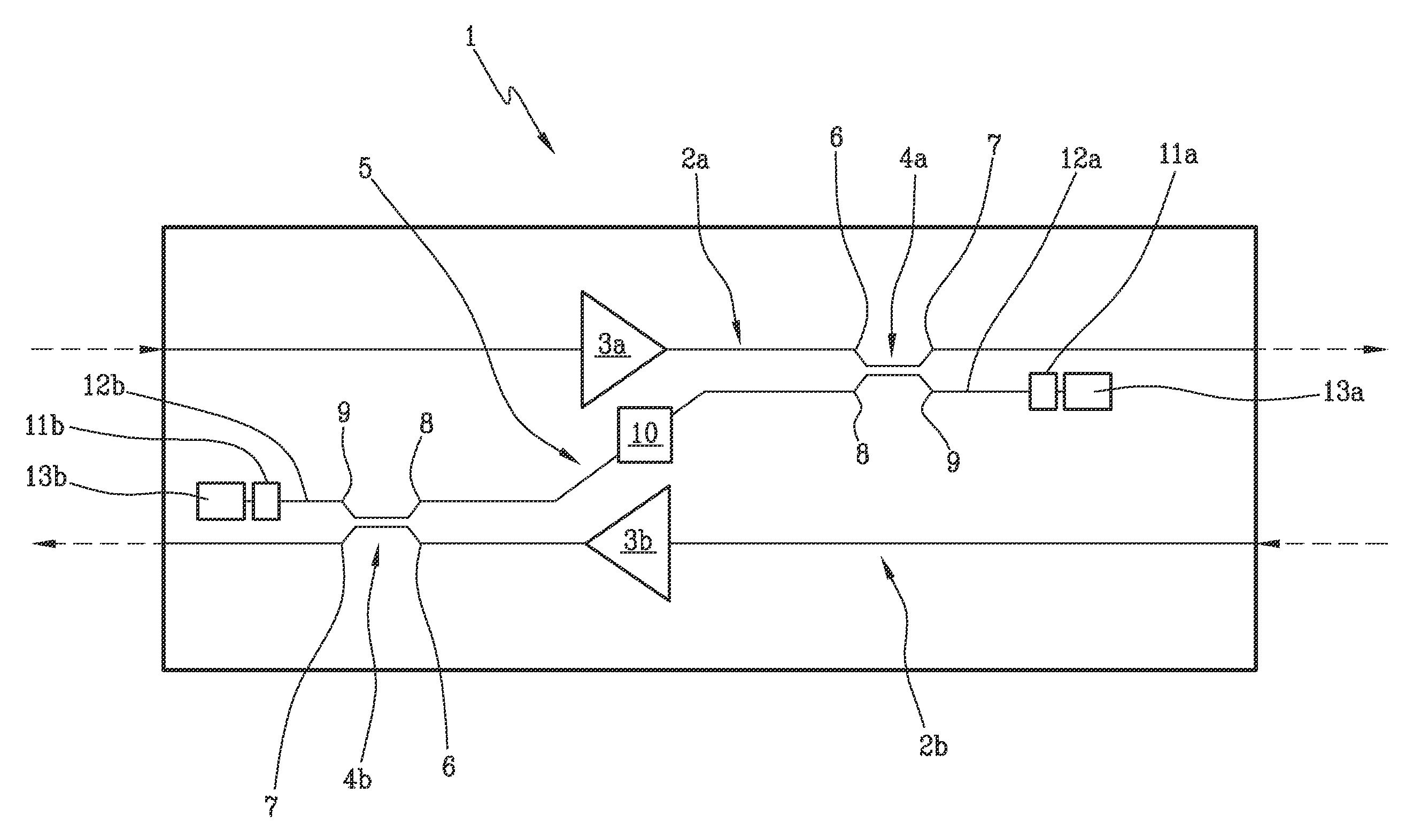
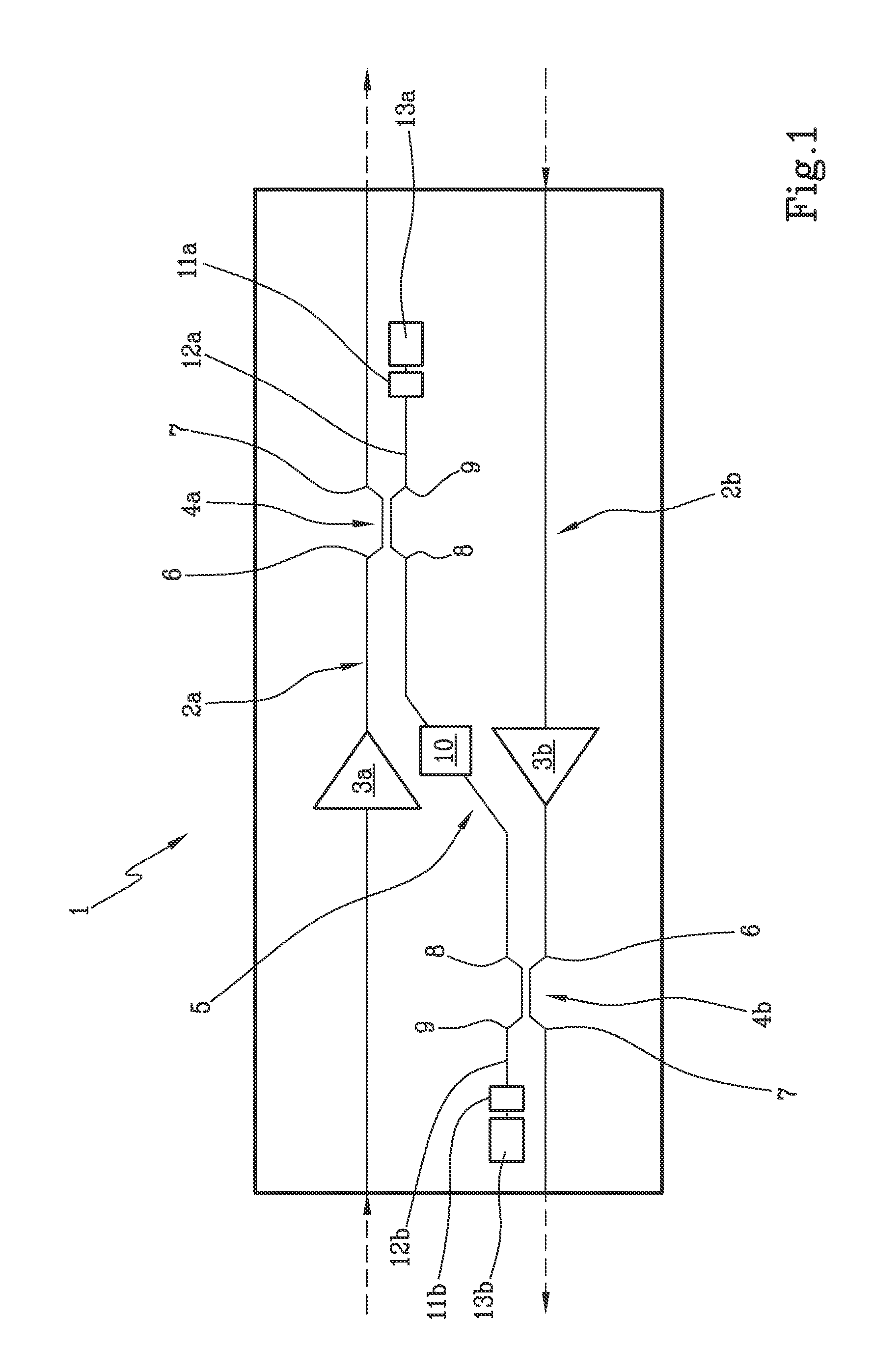
[0043]The optical amplification stage 1 for OTDR monitoring of the present invention comprises a first and a second optical signal path 2a, 2b (e.g. mainly composed of optical fibers) having respectively first and second direction of propagation (indicated by the dashed arrows in FIG. 1) of a respective first and second optical signal, the first and second direction of propagation being mutually opposite, and a first and a second optical amplifier 3a, 3b located along the first and second optical signal path respectively and having an optical amplification band, typically equal for the two amplifiers.

[0044]Typically each of the first and second optical signal is a WDM signal comprising a plurality of optical signal channels having center wavelengths distributed on a grid equally spaced in frequency by a WDM spacing (e.g. equal to 100 GHz or 50 GHz), the WDM signal occupying a WDM band comprised within the amplification band. Exemplarily, the width of the (single spectrally continuou...


PUM


Abstract

Optical amplification stage (1) for OTDR monitoring, comprising a first (2a) and a second optical signal path (2b), a first (3a) and a second optical amplifier (3b), a first optical coupler (4a) placed along the first optical signal path downstream the first optical amplifier, a second optical coupler (4b) placed along the second optical signal path downstream the second optical amplifier, an optical by-pass path (5) optically connecting the first and the second optical coupler, a first (11a) and a second optical reflector (11b) optically connected to respectively the first and second optical coupler, and an optical filter (10) placed along the optical by-pass path which has attenuation high on the whole WDM band and low at the OTDR wavelength(s).

Description

FIELD OF THE INVENTION[0001]The present invention relates to the field of optical telecommunication, in particular it relates to an optical amplification stage for OTDR monitoring and related method and system for OTDR monitoring of an optical communication link, in particular a bi-directional, amplified, optical communication link.BACKGROUND OF THE INVENTION[0002]Optical Time Domain Reflectometry (OTDR), and more particularly Coherent-OTDR (C-OTDR, e.g. having an OTDR signal based on a continuous wave shifted in frequency and received coherently), is a well known technique for monitoring optical communication link made up of optical fiber spans, in particular for monitoring amplified optical communication link wherein a number of optical amplifiers are cascaded along the optical communication link. For example, in submarine optical communication systems which may span over thousands of kilometers (up to 8-10.000 km) without opto-electronic (O / E) conversion of the WDM signal thanks ...

Claims


Application Information

Patent Timeline
IPC IPC(8): H04B10/071H04B10/291
CPCH04B10/071H04B10/2918H04B10/298
Inventor GRASSO, GIORGIOMELLONI, ANDREARIGHETTI, ALDOMELI, FAUSTO
Owner SUBCOM BRASIL COMML LTDA
Why Eureka
Try Eureka