Acoustic wave filter device and duplexer

a filter device and filter device technology, applied in the direction of piezoelectric/electrostrictive/magnetostrictive devices, electrical apparatus, impedence networks, etc., can solve the problem of difficulty in obtaining a sufficient attenuation in an attenuation band, and achieve the effect of preventing an effect on the passband, and sufficient attenuation

Active Publication Date: 2007-10-11
MURATA MFG CO LTD
View PDF10 Cites 4 Cited by
  • Summary
  • Abstract
  • Description
  • Claims
  • Application Information

AI Technical Summary

Benefits of technology

[0028] In the acoustic wave filter device having a balance-to-unbalance transforming function according to the third and fourth preferred embodiments of the present invention, the first and second longitudinally coupled resonator acoustic wave filters are connected in parallel to the unbalanced signal terminal, the third and fourth longitudinally coupled resonator acoustic wave filters are connected in the subsequent stage of the first and second longitudinally coupled resonator acoustic wave filters, and the third and fourth longitudinally coupled resonator acoustic wave filters are connected to the first and second balanced signal terminals. The first and second longitudinally coupled resonator acoustic wave filters or the third and fourth longitudinally coupled resonator acoustic wave filters are withdrawal-weighted. The withdrawal weighting is different between the first and second longitudinally coupled resonator acoustic wave filters or the third and fourth longitudinally coupled resonator acoustic wave filters. Accordingly, the attenuation in the attenuation band near the passband can be controlled without significantly affecting the passband. For example, a sufficient attenuation can be obtained in the attenuation band on the lower frequency side of the passband.
[0029] When the withdrawal weighting is performed in an asymmetrical manner with respect to the center of the withdrawal-weighted longitudinally coupled resonator acoustic wave filter in the acoustic wave propagating direction, the attenuation in the attenuation band near the passband can be further increased.
[0030] When the number of electrode fingers on which the withdrawal weighting is performed is equal among the withdrawal-weighted longitudinally coupled resonator acoustic wave filters, the attenuation in the attenuation band near the passband can be adjusted by the manner of withdrawal weighting with further preventing an effect on the passband.
[0031] When the withdrawal weighting is performed on the corresponding IDTs among the plurality of longitudinally coupled resonator acoustic wave filters, the attenuation in the attenuation band near the passband can be adjusted by the manner of withdrawal weighting with further preventing an effect on the passband.
[0032] When all of the IDTs are withdrawal-weighted, an attenuation-frequency characteristic can be adjusted more effectively.
[0033] A duplexer according to other preferred embodiments of the present invention includes the acoustic wave filter device according to preferred embodiments of the present invention. Accordingly, a sufficient attenuation can be obtained near the passband without significantly affecting the filter characteristic in the passband. Also, by using the acoustic wave filter device of preferred embodiments of the present invention as at least one of bandpass filters on receiver and transmitter sides, the filter characteristic on the receiver side and / or the transmitter side can be effectively improved.

Problems solved by technology

However, it is difficult to obtain a sufficient attenuation in an attenuation band near a passband.

Method used


Image

  • Acoustic wave filter device and duplexer
  • Acoustic wave filter device and duplexer
  • Acoustic wave filter device and duplexer

Examples


Embodiment Construction

[0047] Hereinafter, the present invention is described by describing specific preferred embodiments of the present invention with reference to the drawings.

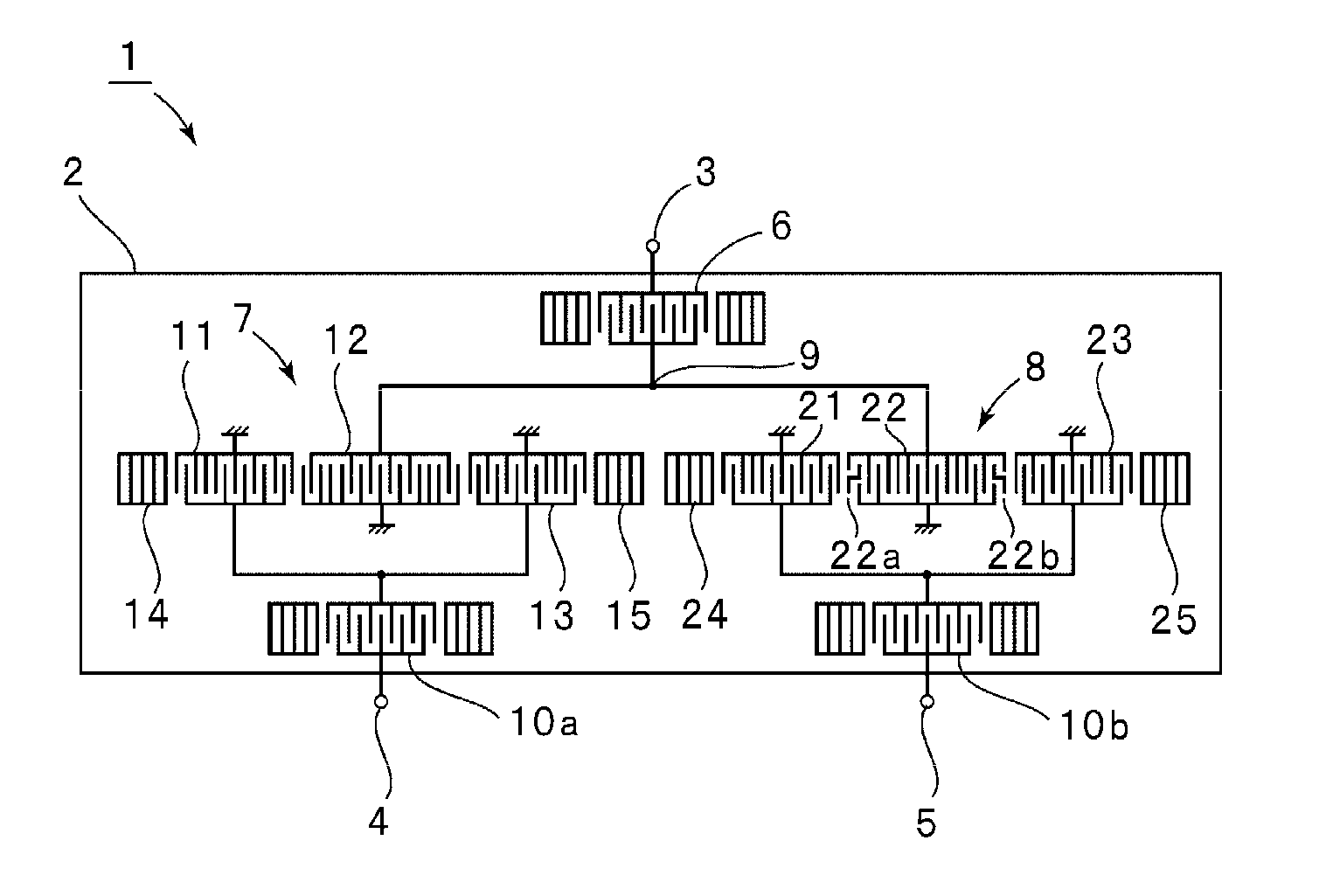
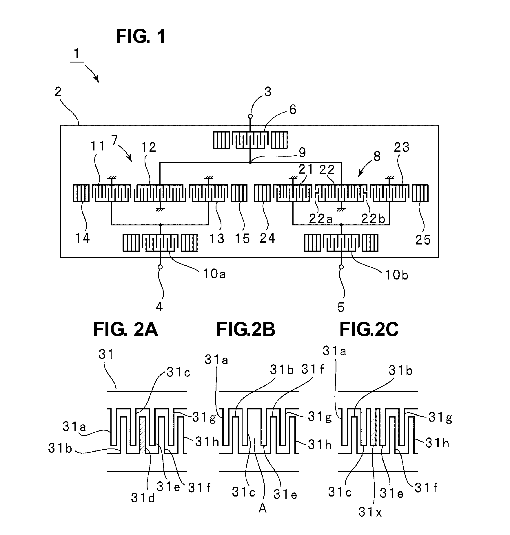
[0048]FIG. 1 is a schematic plan view showing an electrode configuration of a surface acoustic wave (SAW) filter device 1 according to a first preferred embodiment of the present invention. The SAW filter device 1 includes a piezoelectric substrate 2. In this preferred embodiment, a 42°-rotated Y-cut X-propagating LiTaO3 substrate is preferably used as the piezoelectric substrate 2, for example.

[0049] The SAW filter device 1 includes an unbalanced signal terminal 3 as an input terminal, and first and second balanced signal terminals 4 and 5 as output terminals. First and second longitudinally coupled resonator SAW filters 7 and 8 are connected to the unbalanced signal terminal 3 via a one-terminal-pair SAW resonator 6. The first and second longitudinally coupled resonator SAW filters 7 and 8 include first to third interdigital ...


PUM


Abstract

In an acoustic wave filter device, first and second longitudinally coupled resonator SAW filters are provided on a piezoelectric substrate. The first and second longitudinally coupled resonator SAW filters are connected in parallel to each other. The first and second longitudinally coupled resonator SAW filters are withdrawal-weighted. The withdrawal weighting in at least the longitudinally coupled resonator SAW filter is different from the withdrawal weighting in the other longitudinally coupled resonator SAW filter.

Description

BACKGROUND OF THE INVENTION [0001] 1. Field of the Invention [0002] The present invention relates to an acoustic wave filter device using surface acoustic waves or boundary acoustic waves and a duplexer. More specifically, the present invention relates to an acoustic wave filter device having a configuration in which interdigital transducers (IDTs) are withdrawal-weighted and a duplexer. [0003] 2. Description of the Related Art [0004] Conventionally, various types of surface acoustic wave (SAW) filter devices have been used as bandpass filters of mobile communication apparatuses. The SAW filter devices include a plurality of longitudinally coupled resonator SAW filters connected in parallel. [0005] For example, Japanese Unexamined Patent Application Publication No. 8-181566 (Patent Document 1) discloses a configuration in which first and second longitudinally coupled resonator SAW filter units are connected in parallel to an input terminal. Each of the first and second longitudinall...

Claims


Application Information

Patent Timeline
Patent Type & Authority Applications(United States)
IPC IPC(8): H03H9/72H03H9/64
CPCH03H9/0071H03H9/0085H03H9/02748H03H9/14526H03H9/14532H03H9/14582H03H9/14585H03H9/6476H03H9/725H03H9/14576H03H9/145H03H9/64H03H9/72
Inventor TAKAMINE, YUICHI
Owner MURATA MFG CO LTD
Why Eureka
Try Eureka