High-frequency filter circuit, high-frequency front end circuit, and communication device

a filter circuit and high-frequency technology, applied in the field of high-frequency filter circuits, can solve the problems of difficult to secure sufficient attenuation in the attenuation band at a frequency lower than the resonant frequency of the parallel, and the low-frequency side of the low-frequency pass band cannot be switched to a frequency

Active Publication Date: 2019-03-28
MURATA MFG CO LTD
View PDF4 Cites 5 Cited by
  • Summary
  • Abstract
  • Description
  • Claims
  • Application Information

AI Technical Summary

Benefits of technology

[0049]With the high-frequency filter circuit and so forth according to the present disclosure, sufficient attenuation can be secured in an attenuation band at a frequency lower than the resonant frequency of a parallel arm resonator.

Problems solved by technology

However, in the configuration of the related art described above, since the resonant frequency of the parallel arm circuit when the switch is in a non-conductive state is a resonant frequency that is higher than the resonant frequency of the parallel arm resonator of the parallel arm circuit, the frequency of the attenuation pole of the low-frequency side of the pass band cannot be switched to a frequency that is lower than the resonant frequency of the parallel arm resonator.
Therefore, there is a problem in that it is difficult to secure sufficient attenuation in an attenuation band at a frequency lower than the resonant frequency of the parallel arm resonator.

Method used


Image

  • High-frequency filter circuit, high-frequency  front end circuit, and communication device
  • High-frequency filter circuit, high-frequency  front end circuit, and communication device
  • High-frequency filter circuit, high-frequency  front end circuit, and communication device

Examples


embodiment 1

1. Circuit Configuration of Communication Device

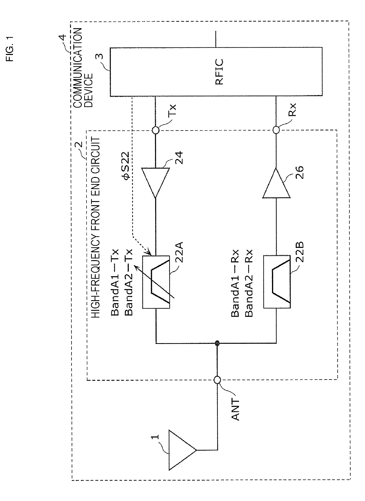
[0078]FIG. 1 is a configuration diagram of a communication device 4 according to embodiment 1. As illustrated in the diagram, the communication device 4 includes an antenna element 1, a high-frequency front end circuit 2, and a radio frequency integrated circuit (RFIC) 3. The communication device 4 is a cellular phone that supports multiple modes / multiple bands, for example. The antenna element 1, the high-frequency front end circuit 2, and the RFIC 3 are arranged in a front end unit of the cellular phone, for example.

[0079]The antenna element 1 is an antenna that transmits and receives high-frequency signals and supports multiple bands in accordance with communication standards such as those of the third generation partnership project (3GPP), for example. The antenna element 1 does not need to support all of the bands of the communication device 4, and may support just the bands of a low frequency band group or a high frequency band g...

embodiment 2

[0274]Embodiment 1 and the modification thereof described above illustrate filters each of which includes one first series circuit 14 or 14D that is formed of a switch element and a second impedance element. In contrast, embodiment 2 illustrates a filter that includes a plurality of the first series circuits.

[0275]FIG. 9 is a circuit configuration diagram of a filter 22E according to embodiment 2.

[0276]Compared with the filter 22A according to embodiment 1, the filter 22E illustrated in the figure includes a plurality of first series circuits each comprising of a switch element and a second impedance element (inductor in this case).

[0277]Specifically, similarly to the filter 22A, the filter 22E includes the series arm resonator 22s, the parallel arm resonator 22p, and the capacitor 22C (first impedance element). In addition, the filter 22E includes a plurality of switches 22SWa to 22SWk and a plurality of inductors 22La to 22Lk (second impedance elements). Here, the plurality of swi...

modification 1

of Embodiment 2

[0283]Embodiment 2 described above, as an example, illustrates a filter in which a capacitor is used as the first impedance element and inductors are used as the second impedance elements. However the relationship between these elements may be reversed. In other words, an inductor may be used as the first impedance element and capacitors may be used as the second impedance elements. Accordingly, in modification 1 of embodiment 2, this kind of filter will be described.

[0284]FIG. 10 is a circuit configuration diagram of a filter 22F according to modification 1 of embodiment 2.

[0285]Compared with the filter 22D according to modification 1 of embodiment 1, the filter 22F illustrated in the figure includes a plurality of first series circuits each comprising of a switch element and a second impedance element (capacitor in this case). Here, the first series circuits are each a circuit obtained by interchanging an inductor and a capacitor in the first series circuit in embod...


PUM


Abstract

A filter (22A) includes: a series arm circuit (11) that is connected between an input/output terminal (22m) and an input/output terminal (22n); and a parallel arm circuit (12) that is connected between a node (x1), which is on a path that connects the input/output terminal (22m) and the input/output terminal (22n), and ground. The parallel arm circuit (12) includes a parallel arm resonator (22p) and an impedance circuit (13) that is serially connected to the parallel arm resonator (22p). The impedance circuit (13) includes a first impedance element, which is one of an inductor and a capacitor, a second impedance element, which is the other of an inductor and a capacitor, and a switch (22SW) that is serially connected to the second impedance element. A first series circuit (14) comprising of the second impedance element and the switch (22SW) is connected in parallel with the first impedance element.

Description

[0001]This is a continuation of International Application No. PCT / JP2017 / 019792 filed on May 26, 2017 which claims priority from Japanese Patent Application No. 2016-106802 filed on May 27, 2016. The contents of these applications are incorporated herein by reference in their entireties.BACKGROUND OF THE DISCLOSUREField of the Disclosure[0002]The present disclosure relates to a high-frequency filter circuit that includes resonators, to a high-frequency front end circuit, and to a communication device.Description of the Related Art[0003]Heretofore, elastic wave filters that employ elastic waves have been widely used in band pass filters and so on that are arranged in the front end units of mobile communication devices. In addition, high-frequency front end circuits have been implemented that include a plurality of elastic wave filters in order to support combinations such as multiple modes, multiple bands, and so on.[0004]For example, a ladder filter structure formed of a series arm ...

Claims


Application Information

Patent Timeline
Patent Type & Authority Applications(United States)
IPC IPC(8): H03H9/64H03H9/54H04B1/40H03H7/46
CPCH03H9/6406H03H9/542H04B1/40H03H7/46H03H9/0542H03H9/6403H03H9/6483H04B1/0053H04B1/0458H04B1/20H03H7/01H03H9/64H03H9/72
Inventor NOSAKA, KOJI
Owner MURATA MFG CO LTD
Why Eureka
Try Eureka