
3D printed reflector and method for its manufacture

a 3d printed reflector and manufacturing method technology, applied in the direction of reflex reflectors, additive manufacturing processes, instruments, etc., can solve the problems of relatively low thermal conductivity and inability to meet the needs of injection molding applications, and achieve the effects of optimizing reflection, shortening path length, and prolonging path length

Active Publication Date: 2019-05-30
SIGNIFY HLDG BV
View PDF0 Cites 0 Cited by
  • Summary
  • Abstract
  • Description
  • Claims
  • Application Information

AI Technical Summary

Benefits of technology

The invention is related to a method of creating custom shapes using FDM printers, which can be used to produce LED luminaires and lighting solutions. The technique involves heating and extruding a polymer through a fine nozzle to create a 3D model. The resulting shapes have certain structures on both sides, which affect their optical performance. The patent proposes a method to change the shape of each individual line to achieve the desired optical performance, without additional tooling cost. The FDM printing technology allows for easy control of the dimensions and reflective properties of the filaments. A non-imaging reflector with the desired reflective properties can be created by optimizing TIR. The patent also discusses the importance of a gradient in the corrugation properties of the reflector to achieve highest specular reflection.

Problems solved by technology

While this technique produces smooth surfaces the photo curable materials are not very stable and they also have relatively low thermal conductivity to be useful for injection molding applications.

Method used


Image

  • 3D printed reflector and method for its manufacture
  • 3D printed reflector and method for its manufacture
  • 3D printed reflector and method for its manufacture

Examples


Embodiment Construction

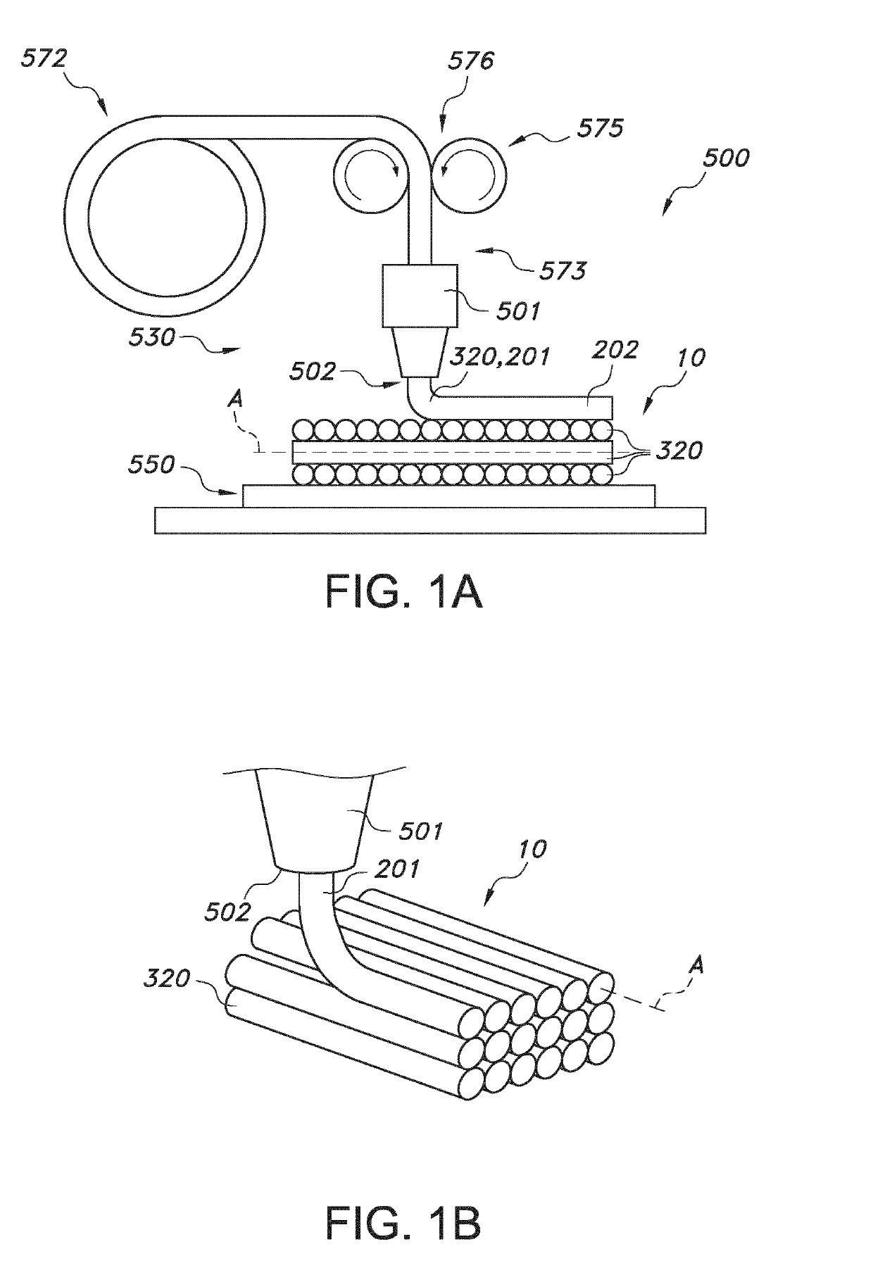
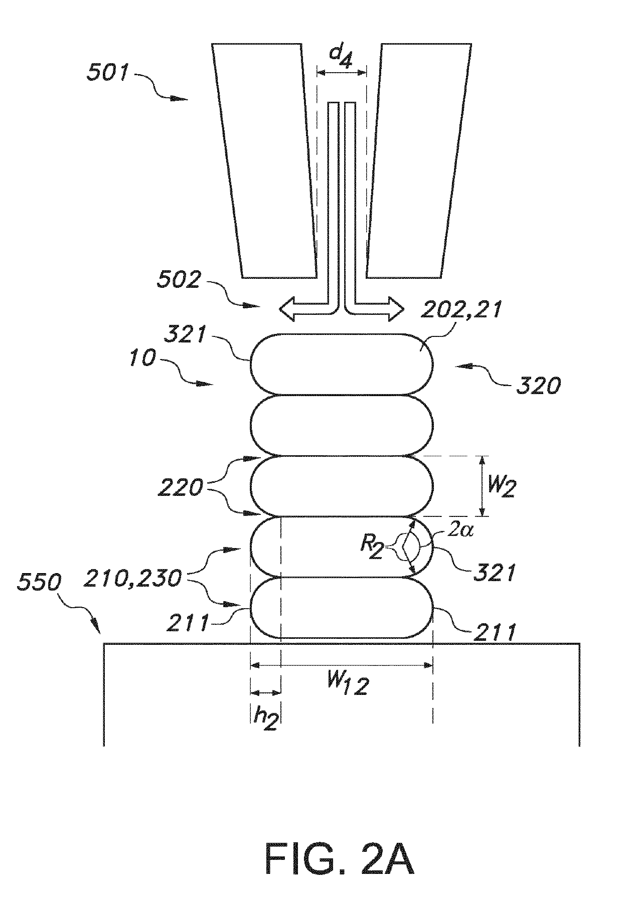
[0058]FIG. 1a schematically depicts some aspects of the 3D printer. Reference 500 indicates a 3D printer, herein also indicated as fused deposition modeling 3D printer. Reference 530 indicates the functional unit configured to 3D print, especially FDM 3D printing; this reference may also indicate the 3D printing stage unit. Here, only the printer head for providing 3D printed material, such as a FDM 3D printer head is schematically depicted. Reference 501 indicates the printer head. The 3D printer of the present invention may especially include a plurality of printer heads, though other embodiments are also possible. Reference 502 indicates a printer nozzle. The 3D printer of the present invention may especially include a plurality of printer nozzles, though other embodiments are also possible. Reference 320 indicates a filament of printable 3D printable material (such as indicated above). For the sake of clarity, not all features of the 3D printer have been depicted, only those tha...


PUM

PropertyMeasurementUnit
reflectanceaaaaaaaaaa
angleaaaaaaaaaa
angleaaaaaaaaaa

Abstract

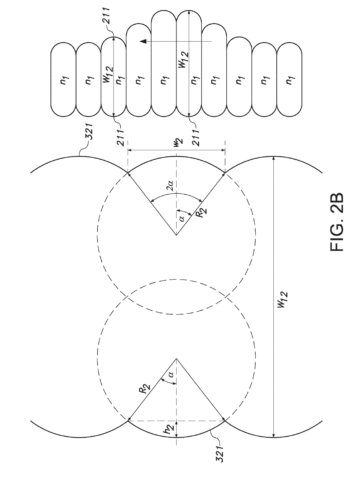
The invention provides a reflector (2) comprising a reflector wall (20), the reflector wall (20) comprising a first wall surface (22) and a second wall surface (23) defining said reflector wall (20), the reflector wall (20) comprising a light transmissive material (21), wherein the reflector wall (20) has a first dimension (d1) and a second dimension (d2) defining a first reflector wall area, wherein each wall surface (22,23) comprises a plurality of parallel arranged elongated corrugations (210), wherein the corrugations have corrugation heights (h2) relative to recesses (220) between adjacent corrugations (210) and corrugation widths (w2) defined by the distance between adjacent recesses (220) at the respective wall surfaces (22,23), wherein the corrugations (210) have curved corrugation surfaces (230) between said adjacent recesses (220) having corrugation radii (r2) at the respective wall surfaces (22,23), and wherein over at least part of one of the first dimension (d1) and the second dimension (d2) one or more of (i) the corrugation heights (h2), (ii) the corrugation widths (w2), (iii) the corrugation radii (r2), and (iv) a shortest top-top distance (w12) of corrugations tops (211) configured at different wall surfaces (22,23) vary over said wall dimension (d1,d2) for at least one of the wall surfaces (22,23). The reflector (2) has a first end (3) and a second end (4), wherein a third distance (d3) between the first end (3) and the second end (4) is bridged by one or more reflector walls (20), wherein the one or more reflector walls (20) are configured tapering from the second end (4) to the first end (3), and wherein the reflector (2) has a reflector cavity (5).

Description

FIELD OF THE INVENTION[0001]The invention relates to a method for manufacturing a 3D item. The invention also relates to the 3D (printed) item obtainable with said method. Further, the invention relates to a software product that can be used to execute such method. Yet further, the invention relates to a lighting system including such 3D (printed) item.BACKGROUND OF THE INVENTION[0002]Additive manufacturing parts of optical systems is known in the art. US20150343673 A1, for instance, describes a method of manufacturing an optical-element, comprising (a) printing at least a part of a mold via additive manufacturing technology, (b) depositing a nanocomposite-ink at one or more voxels within the mold, (c) selectively curing the deposited nanocomposite-ink, and (d) repeating at least steps (b) through (d) until the mold is appropriately filled and cured. The mold is made from a plastic. In embodiments, the mold incorporates an optical insert. The optical insert is incorporated during th...

Claims


Application Information

Patent Timeline
Patent Type & Authority Applications(United States)
IPC IPC(8): B29D11/00B29C64/112B29C64/209
CPCB29D11/00605B29C64/112B29C64/209B29K2069/00B33Y70/00B33Y80/00B29C64/106G02B5/0215G02B5/13G02B5/136G02B19/0028G02B19/0061
Inventor BOONEKAMP, ERIK PAULVAN HAL, PAULUS ALBERTUSHIKMET, RIFAT ATA MUSTAFA
Owner SIGNIFY HLDG BV
Learn More