MEMS millimeter wave switches

a technology waveguides, applied in the field of millimeter wave switches, can solve the problems of reducing the rf power capability of the switch, unsuitable commercial applications, and relative high rf power losses, so as to reduce the rf power loss of the switch, increase the rf power handling capability, and shorten the conduction path length in the air bridge

Inactive Publication Date: 2005-03-29
NORTHROP GRUMMAN SYST CORP
View PDF5 Cites 4 Cited by
  • Summary
  • Abstract
  • Description
  • Claims
  • Application Information

AI Technical Summary

Benefits of technology

Briefly, the present invention relates to various embodiments of an RF switch suitable for use at millimeter wave and higher frequencies of 30 GHz and above. All embodiments of the switch are configured to reduce portions of the switch structure which are not 50 ohm transmission lines in order to reduce the RF power losses of the switch and increase its RF power handling capability. Four embodiments of the invention are configured as ground switches. Two of the ground switch embodiments are configured with a planar air bridge. Both of these embodiments are configured so that the conduction path length in the air bridge is shortened between the transmission line and ground by introducing grounded stops. The other two ground switch embodiments include an elevated metal seesaw. In these embodiments, a shortened path to ground is provided with relatively low inductance by proper sizing and positioning of the seesaw structure. Lastly, a broadband power switch embodiment is configured to utilize only a small portion of the air bridge to carry the signal. The relatively short path length results in a relatively low inductance and resistance which reduces the RF power losses of the switch and increases its RF power handling capability relative to known RF switches.

Problems solved by technology

Although such a configuration provides satisfactory performance, such a configuration has a relatively high impedance (i.e. relatively high inductive and resistance) which results in relatively high RF power losses, and reduces the RF power capability of the switch.
Although such capacitive-type switches provide adequate performance in the millimeter wave and microwave frequencies, the dielectric layer in the capacitive-type switches is known to store charges making it unsuitable for commercial applications.

Method used


Image

  • MEMS millimeter wave switches
  • MEMS millimeter wave switches
  • MEMS millimeter wave switches

Examples


Embodiment Construction

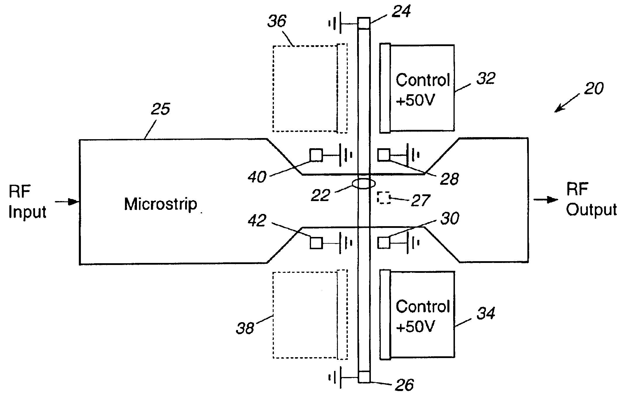
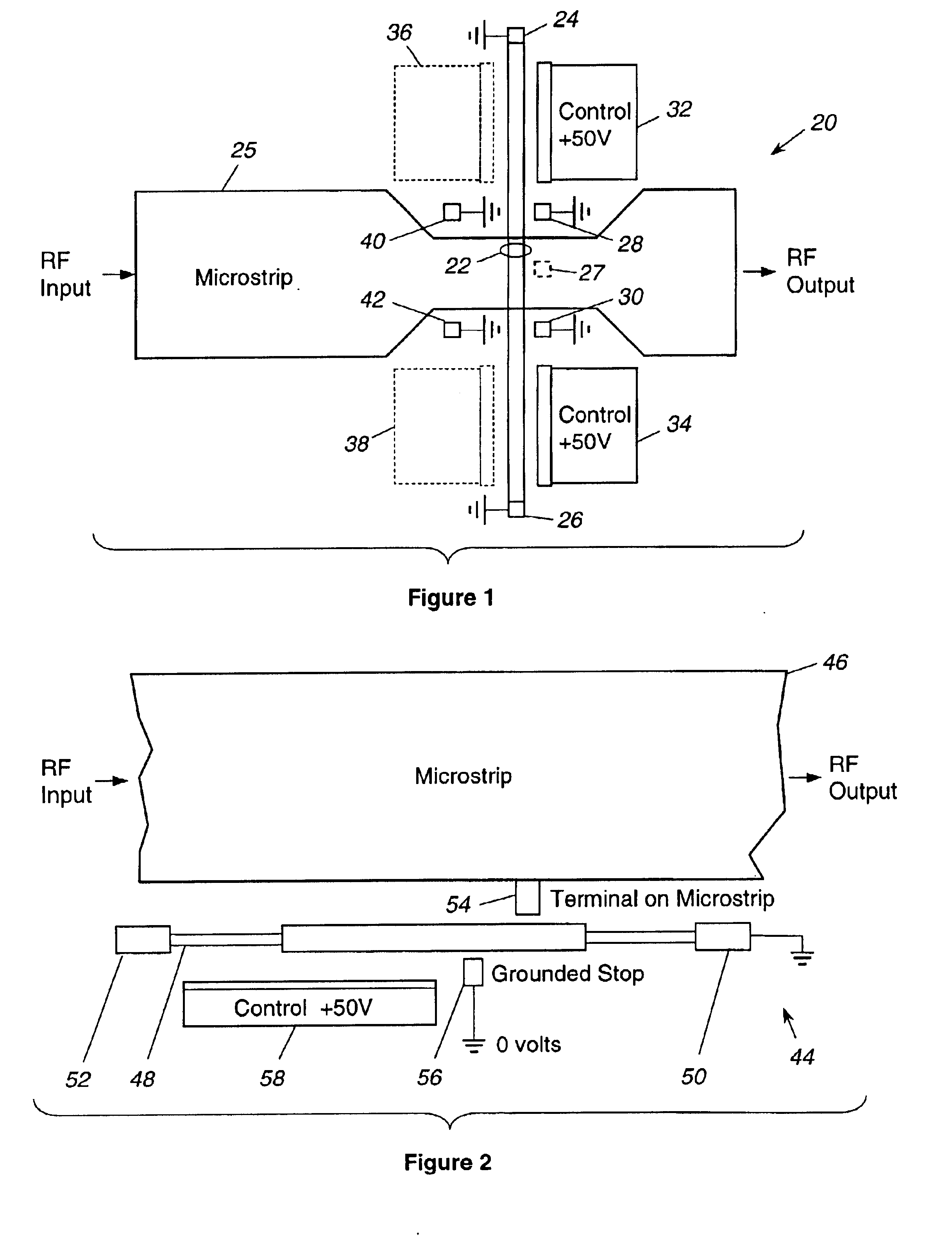
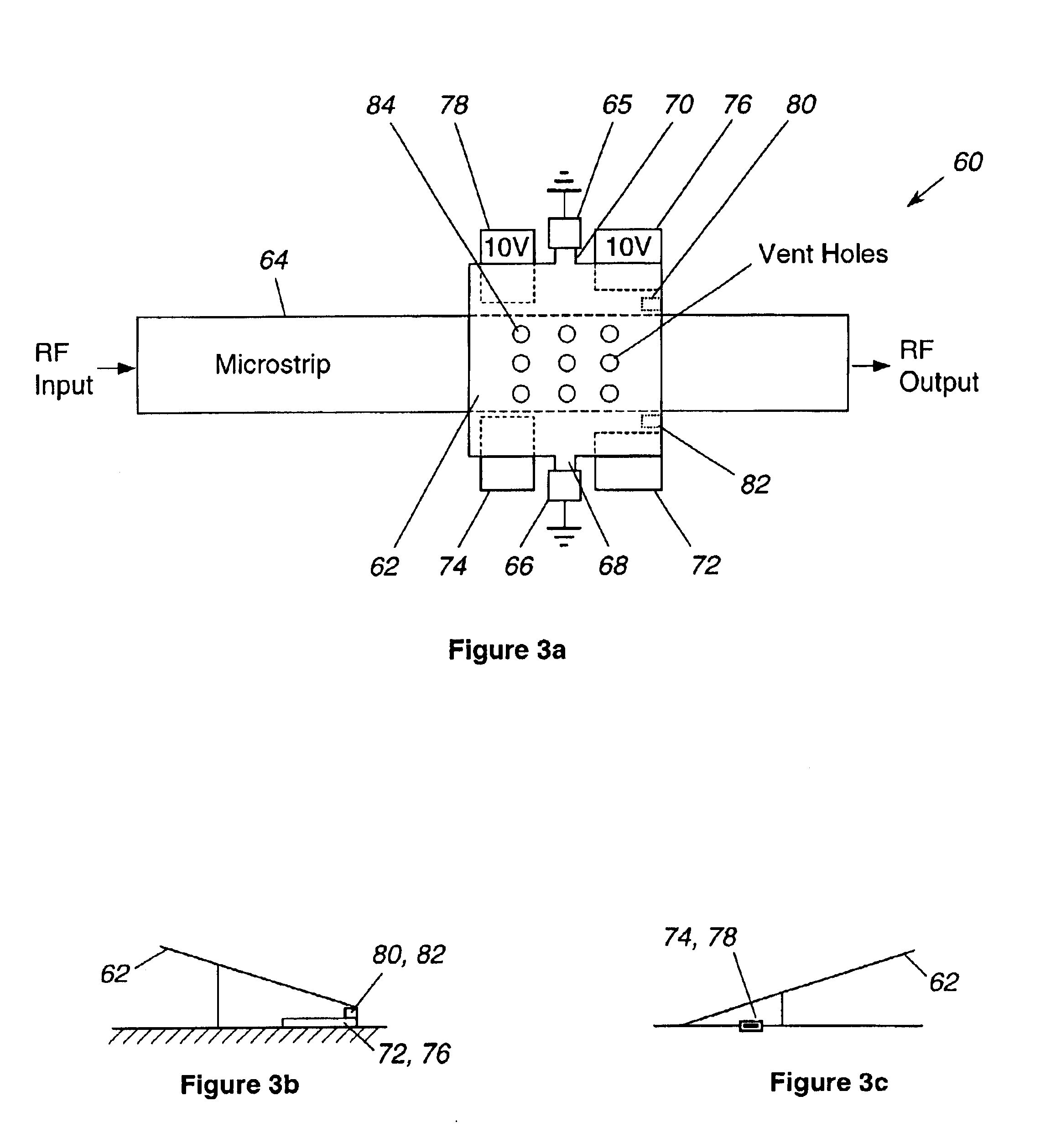
In accordance with the present invention, various embodiments of millimeter wave switches are illustrated in FIGS. 1-8. In particular, FIGS. 1 and 2 illustrate ground switches which incorporate a planar air bridge. FIGS. 3A and 4 illustrate alternate embodiments of a ground switch formed with an elevated seesaw connected between two fixed posts by way of torsion bars. FIGS. 5-7 illustrate an embodiment of a broadband power switch, shown, for example, as a single pole double throw switch. Finally, FIG. 8 illustrates an embodiment of the broadband power switch, illustrated in FIG. 7, but formed with a pair of transverse air bridges.

In all embodiments, the path lengths between the transmission line and ground are shortened relative to known RF switches. By shortening these path lengths, the inductance and resistance of the structure is thereby lowered, thereby lowering the RF power losses of the switch and increasing its power handling capability.

Two embodiments of a grounding switch f...


PUM


Abstract

An RF switch useable up to millimeter wave frequencies and higher frequencies of 30 GHz and above. Four embodiments of the invention are configured as ground switches. Two of the ground switch embodiments are configured with a planar air bridge. Both of these embodiments are configured so that the bridge length is shortened between the transmission line and ground by introducing grounded stops. The other two ground switch embodiments include an elevated metal seesaw. In these embodiments, a shortened path to ground is provided with relatively low inductance by proper sizing and positioning of the seesaw structure. Lastly, broadband power switch embodiment is configured to utilize only a small portion of the air bridge to carry the signal. The relatively short path length results in a relatively low inductance and resistance lowers the RF power loss of the switch, thereby increasing the RF power handling capability of the switch.

Description

BACKGROUND OF THE INVENTION1. Field of the InventionThe present invention relates to millimeter wave switches and more particularly to millimeter wave switches useful at millimeter wave frequencies and higher frequencies with increased power handling capability relative to known switches, amenable to being fabricated using microelectromechanical system (MEMS) technology.2. Description of the Prior ArtRF switches are used in a wide variety of applications. For example, such RF switches are known to be used in variable RF phase shifters, RF signal switching arrays, switchable tuning elements, as well as band switching of voltage controlled oscillators. In order to reduce the size and weight of such RF switches, microelectromechanical system (MEMS) technology has been known to be used to fabricate such switches. An example of such an RF switch is disclosed in commonly owned U.S. Pat. No. 6,218,911, hereby incorporated by reference. The RF switch disclosed therein includes a pair of rel...

Claims


Application Information

Patent Timeline
Patent Type & Authority Patents(United States)
IPC IPC(8): H01H59/00B81B3/00H01P1/12
CPCH01H59/0009H01P1/10H01P1/127
Inventor STOKES, ROBERT B.KONG, ALVIN M.
Owner NORTHROP GRUMMAN SYST CORP
Why Eureka
Try Eureka