Thin-Film Radio Frequency Power Terminator

a technology of power terminator and thin film, applied in the direction of electrical apparatus construction details, conductive pattern formation, modification by conduction heat transfer, etc., can solve the problems of design challenges and bulky configuration of terminator, and achieve the effect of low physical profile and high power handling capability

Inactive Publication Date: 2015-12-03
JOHNSON MANUFACTURING COMPANY
View PDF0 Cites 15 Cited by
  • Summary
  • Abstract
  • Description
  • Claims
  • Application Information

AI Technical Summary

Benefits of technology

[0005]The present invention relates to a high-power, thin-film radio frequency power terminator. The terminator includes a mounting flange and a thin-film termination chip mounted on a surface of the mounting flange. The mounting flange provides a ground terminal for the termination chip. The termination chip is manufactured using thin-film manufacturing techniques, and includes a substrate, a terminal, a metallization layer including a resistor pad electrically connecting the terminal to the mounting flange, and a cover. Advantageously, the terminator has a low physical profile but provides high power handling capability.

Problems solved by technology

Unfortunately, terminators often have bulky configurations that create design challenges, particularly when the terminators must handle significant (e.g., 1000 Watts or greater) power loads.

Method used


Image

  • Thin-Film Radio Frequency Power Terminator
  • Thin-Film Radio Frequency Power Terminator
  • Thin-Film Radio Frequency Power Terminator

Examples


Embodiment Construction

[0014]The present invention relates to a thin-film, high-power radio frequency terminator, as discussed in detail below in connection with FIGS. 1-7.

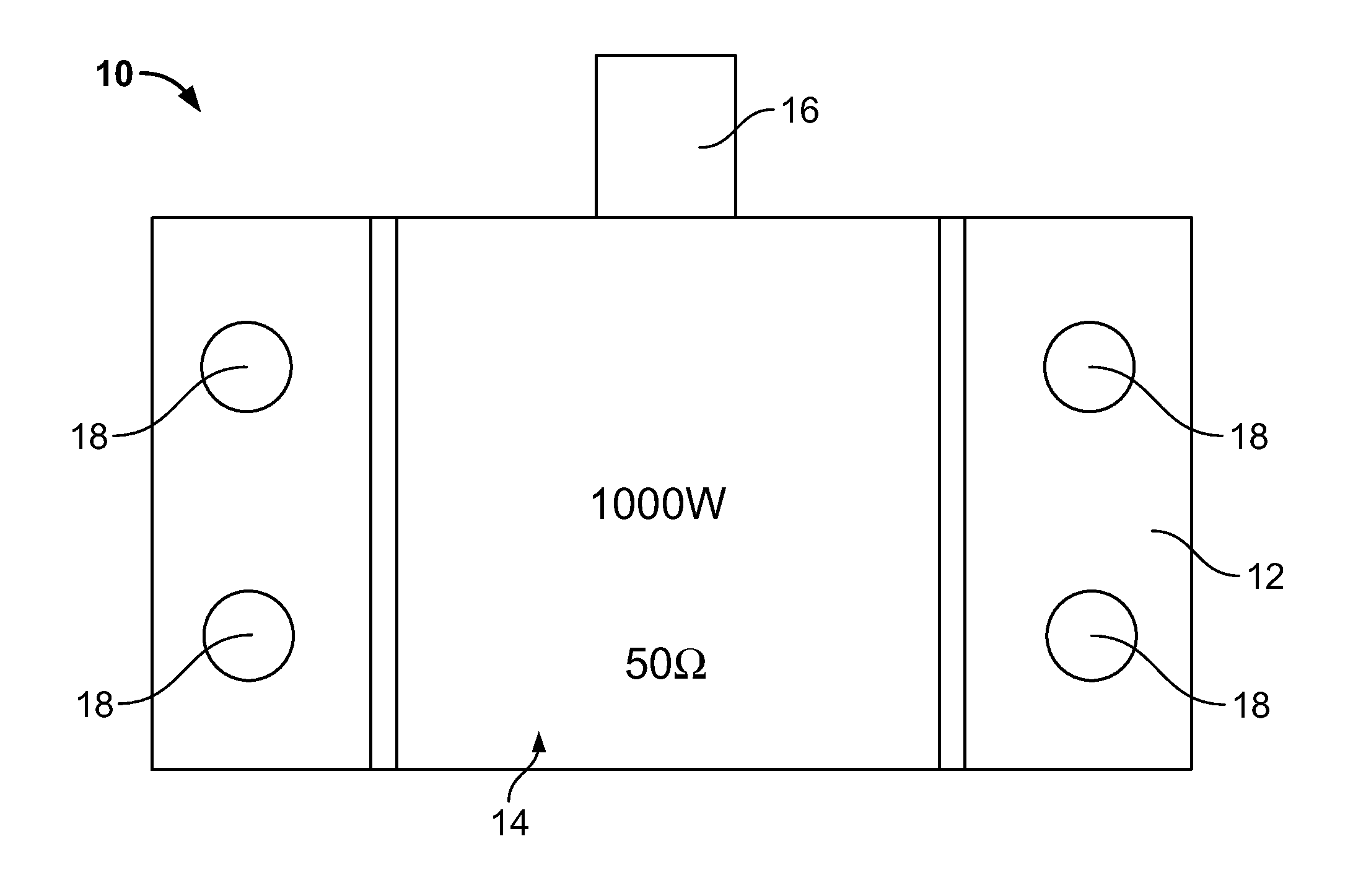
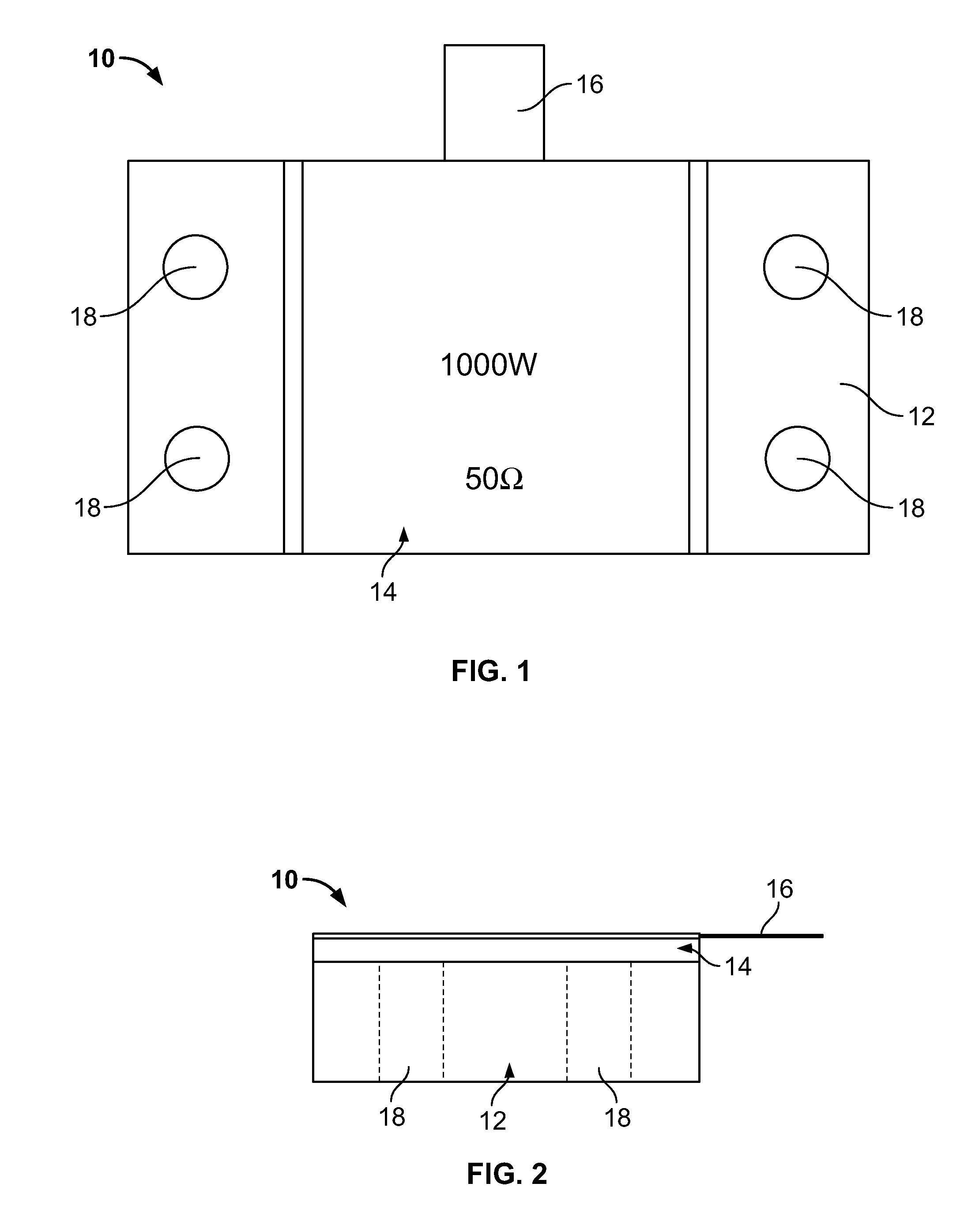
[0015]FIG. 1 is a top view showing the terminator of the present invention, indicated generally at 10. The terminator 10 includes a termination chip 14 that is mounted on a mounting flange 12. As seen in FIG. 1, both the termination chip 14 and the mounting flange 12 have rectangular shapes, but of course, other shapes and / or geometries can be provided. A terminal 16 protrudes from the termination chip 14 and is electrically connectable to an RF circuit. The profile of the mounting flange 12 is greater than that of the termination chip 14 (e.g., mounting flange 12 is wider than the termination chip 14) to accommodate mounting holes 18 on opposite sides of the termination chip 14. As indicated in FIG. 1, the terminator 10 could have a resistance of 50 ohms, but of course, other resistances and / or impedances are possible.

[0016]FIG. 2 is a...


PUM

PropertyMeasurementUnit
poweraaaaaaaaaa
resistancesaaaaaaaaaa
thicknessaaaaaaaaaa

Abstract

A thin-film, radio frequency terminator is provided that includes a mounting flange and a thin-film termination chip mounted on a surface of the mounting flange. The mounting flange grounds the termination chip. The termination chip includes a substrate, a terminal, a metallization layer including a resistor pad electrically connecting the terminal to the mounting flange, and a cover. The terminator has a low physical profile but provides high power handling capability.

Description

BACKGROUND OF THE INVENTION[0001]1. Field of the Invention[0002]The present invention relates to radio frequency (RF) power electronics. More specifically, the present invention relates to a thin-film RF power terminator.[0003]2. Related Art[0004]Terminators provide electrical resistance to present an electrical load to an RF transmitter and an associated transmission line. Additionally, terminators prevent a signal from being reflected back from the end of the transmission line and causing interference. Often, terminators are used in wireless communications networks. For example, a terminator can be incorporated in a transmitter circuit of a wireless node (e.g., a base station, a relay station, a mobile device, etc.). Unfortunately, terminators often have bulky configurations that create design challenges, particularly when the terminators must handle significant (e.g., 1000 Watts or greater) power loads. As such, there is a need to provide high-power RF terminators that have a low...

Claims


Application Information

Patent Timeline
Patent Type & Authority Applications(United States)
IPC IPC(8): H05K7/06H05K3/10
CPCH05K7/06Y10T29/49099H05K3/10H05K7/2039H04B1/00
Inventor IMBIMBO, MARKAEAD, HATEM
Owner JOHNSON MANUFACTURING COMPANY
Why Eureka
Try Eureka