Tri-element antenna with dish

Inactive Publication Date: 2003-07-03
NILSSON JACK +1
View PDF5 Cites 14 Cited by
  • Summary
  • Abstract
  • Description
  • Claims
  • Application Information

AI Technical Summary

Problems solved by technology

Such an antenna can strike many overhead obstructions, causing it to bend and alter the angle of radiation when the vehicle is moving.
Mounting a 10-foot antenna on the roof of a car is not feasibl

Method used


Image

  • Tri-element antenna with dish
  • Tri-element antenna with dish
  • Tri-element antenna with dish

Examples


Embodiment Construction

[0045] The present invention relates to a dipole ground plane antenna for motor vehicles. The antenna may be adapted for use with a multitude of receiving systems such as those used for mobile communications, FM radio, AM radio, passive systems and the like. The antenna provides excellent directional properties, provides broader bandwidth and smoother radiation patterns than antennas of the prior art, and provides substantially easier impedance matching with a selected receiver.

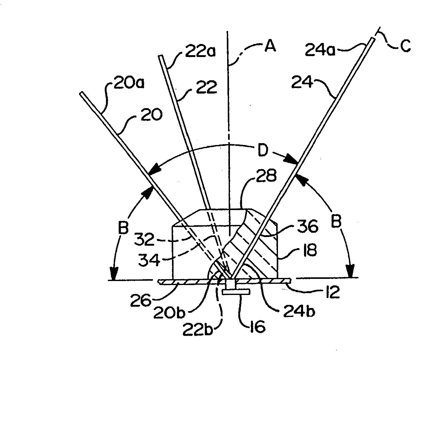
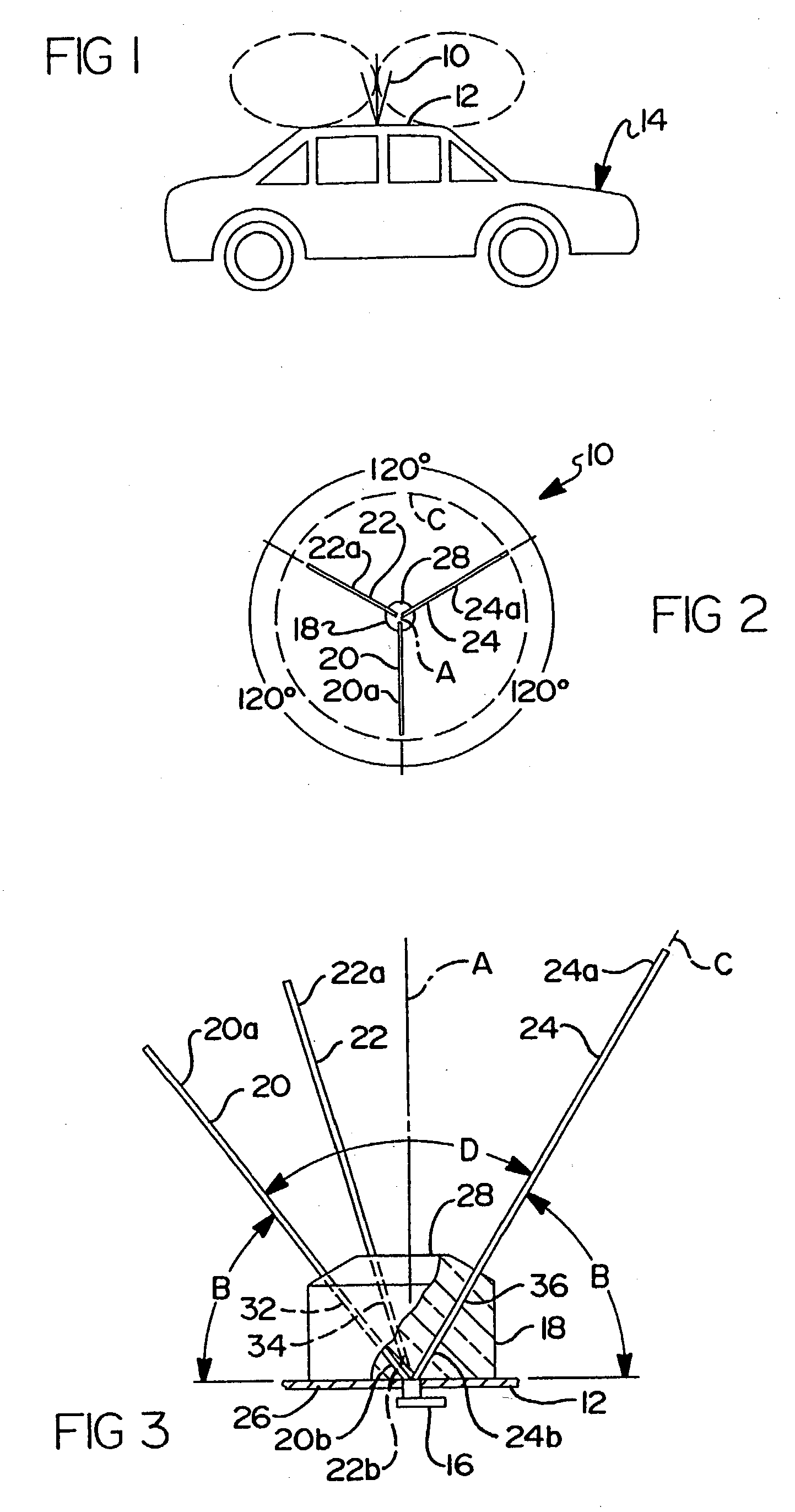
[0046] Turning to FIGS. 1-3, a ground plane antenna 10 of the present invention is particularly suited for motor vehicle applications and is shown mounted to the roof 12 of a motor vehicle 14 and in electrical circuit relation with a transceiver or receiving device 16 of the motor vehicle. The antenna 10 may be installed in almost any motor vehicle such as an automobile, truck, train, or construction equipment and the like. Further, although the antenna is shown secured to the roof of an automobile, the anten...


PUM


Abstract

A three element antenna utilizes a truncated parabolic reflector dish of diameter "d" and focal point "f" and a director plate for receiving and transmitting high frequency signals in conjunction with a substantially horizontal conducting ground plane. The antenna is mounted to a planar transverse end wall, defining the lower truncated end of the parabolic surface, and the antenna elements are proximate to the focal point "f" of the paraboloid that defines the dish. The director plate is positioned at the opening (defining the diameter "d"), is distal to the focal point and the antenna elements, and positions an array of director rods about the antenna elements to focus signals relative to the parabolic surface. The ratio of (f/d) is about 0.01 to about 0.625, and preferably about 0.210.

Description

[0001] This is a Continuation-in-part of co-pending patent application Ser. No. 09 / 803,245, filed Mar. 9, 2001, for "Dual Polarized Antenna", and a Completion Patent Application of co-pending U.S. Provisional Patent Application Serial No. 60 / 368,356, filed on Mar. 28, 2002, for "Tri-Element Antenna With Dish", the disclosures of each hereby incorporated by reference.[0002] 1. Field of the Invention[0003] This invention relates to mobile and base station antennas and more particularly to a dual polarized tri-element (tri-band) antenna for use in vehicles. In a particular aspect, the antenna is used with a parabolic dish reflector and director elements to provide for high gain applications.[0004] 2. Description of Related Art[0005] Currently there is a growing need for wireless mobile telephones. Common places on a vehicle for mounting mobile antennas include the roof, rain gutter, bumper, trunk lid, mirror bracket, fender and the side of the vehicle. The simplest mobile VHF / UHF anten...

Claims


Application Information

Patent Timeline
IPC IPC(8): H01Q1/32H01Q9/44H01Q9/46
CPCH01Q1/3275H01Q9/46H01Q9/44
Inventor NILSSON, JACKBADGER, H. GREGORY
Owner NILSSON JACK
Why Eureka
Try Eureka