Methods and Apparatus for Improved Heat Spreading in Solid State Lighting Systems

a solid-state lighting and heat-spreading technology, applied in lighting and heating equipment, fixed installations, lighting support devices, etc., can solve the problems of increased total cost, inability to meet the needs of many potential purchasers, and inability to meet the needs of lighting, etc., to achieve cost-effectiveness, reduce physical profile, and reduce weight

a solid-state lighting and heat-spreading technology, applied in lighting and heating equipment, fixed installations, lighting support devices, etc., can solve the problems of increased total cost, inability to meet the needs of many potential purchasers, and inability to meet the needs of lighting, etc., to achieve cost-effectiveness, reduce physical profile, and reduce weight

US20080089069A1Active Publication Date: 2008-04-17IDEAL IND LIGHTING LLC

Image

  • Methods and Apparatus for Improved Heat Spreading in Solid State Lighting Systems
  • Methods and Apparatus for Improved Heat Spreading in Solid State Lighting Systems
  • Methods and Apparatus for Improved Heat Spreading in Solid State Lighting Systems

Examples


Embodiment Construction

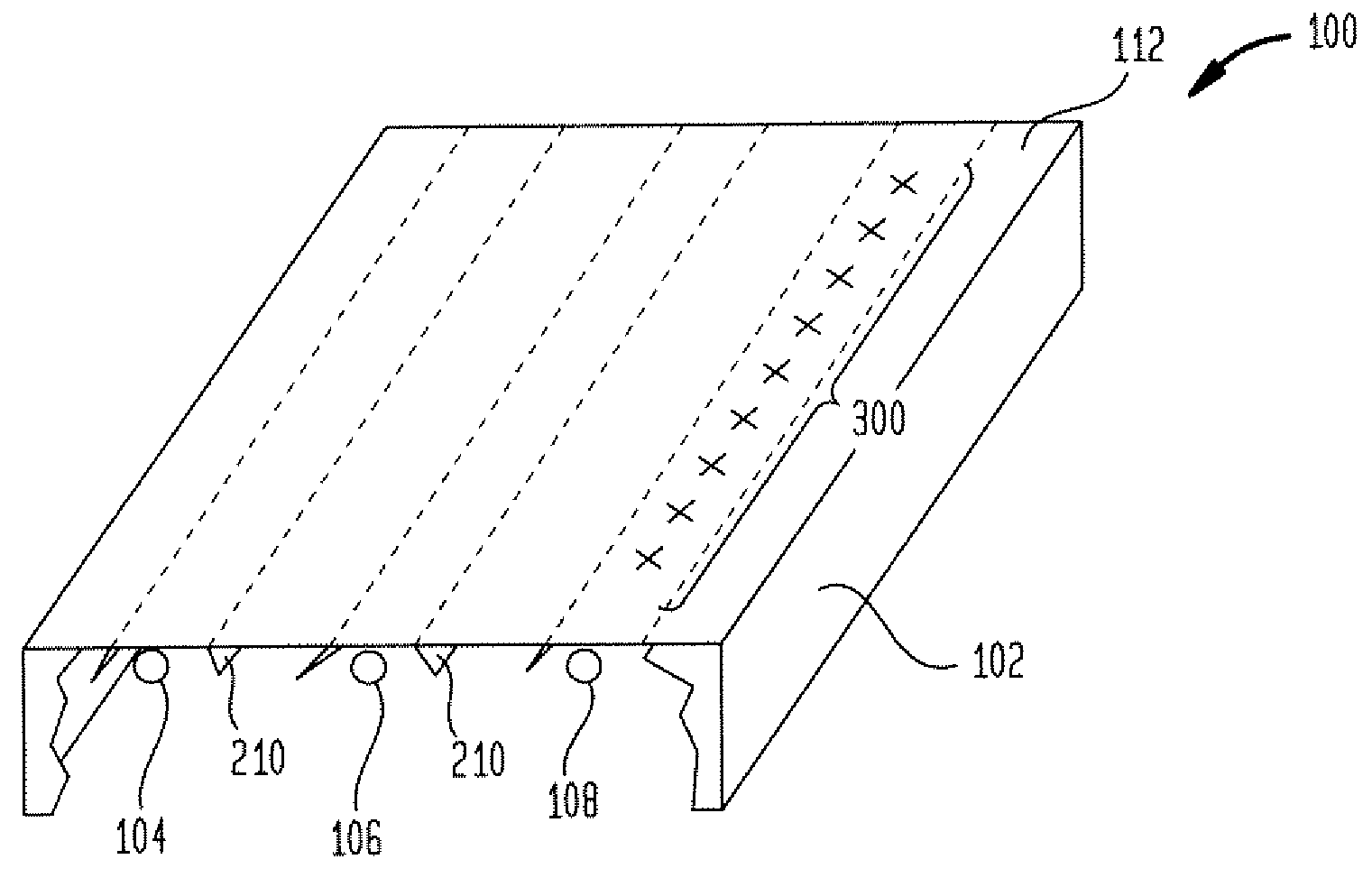
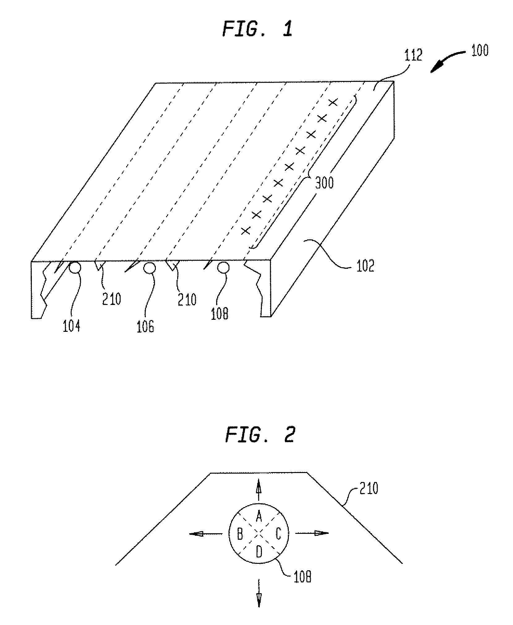
[0023]FIG. 4 shows a side view of a first embodiment of an LED based light fixture 400 in accordance with the present invention. As shown in FIG. 4, each of the three fluorescent bulbs 104, 106, 108 of FIG. 1 is replaced by a number, n, of LEDs 4041, 4042, . . . 404n (collectively 404), 4061, 4062, . . . 406n (collectively 406), and 4081, 4082, . . . 408n (collectively 408), respectively. While it is presently preferred that high power LEDs, such as XLamp™ series LEDs from Cree, Incorporated, having a current of 125 mA or higher be employed, it will be recognized that lower power LEDs may also be employed. Further exemplary details of suitable mounting details of the LEDs 404, 406 and 408 are shown in FIGS. 5, 6, 9A and 9B. While single LEDs are shown, multiple color LEDs, such as red, blue and green may be grouped together in arrays for applications where it is desired to be able to vary the color of light delivered by the fixture.

[0024]In FIGS. 5 and 6, a plurality of LEDs 404 are...


PUM


Abstract

A solid state lighting subassembly or fixture includes an anisotropic heat spreading material. A heat spreading layer may be placed between a light emitting diode (LED) and luminaire or reflector and serves to spread heat laterally away from the LED. Low profile, low weight heat spreading may be utilized both to retrofit existing light fixtures with. LEDs or to replace existing incandescent and fluorescent fixtures with LED based fixtures.

Description

FIELD OF THE INVENTION[0001]The present invention relates generally to improvements to solid state based lighting methods and apparatus suitable for use in both retrofitting and replacing existing fluorescent lighting systems and the like. More particularly, it relates to advantageous methods and apparatus for improved heat spreading and heat management in light emitting diode (LED) lighting systems.BACKGROUND OF THE INVENTION[0002]LED lighting systems are becoming more prevalent as replacements for existing lighting systems. LEDs are an example of solid state lighting and are superior to traditional lighting solutions such as incandescent and fluorescent lighting because they use far less energy, are far more durable, operate longer, can be combined in red-blue-green arrays that can be controlled to deliver virtually any color light, and contain no lead or mercury. As LEDs replace the typical fluorescent light fixtures found in many workplaces, the present invention recognizes that...

Claims


Application Information

Patent Timeline
17 Apr 2008
Publication
US20080089069A1
IPC
F21V29/00
CPC
F21S2/005; F21S6/00; F21S8/04; F21V29/763; F21Y2101/02; F28F3/02; F28F21/02; F21V29/004
Inventors
MEDENDORP, NICHOLAS W.