Method for enhancing selectivity and recovery in the fractional flotation of particles in a flotation column

a technology of fractional flotation and selectivity, which is applied in the direction of flotation, solid separation, etc., can solve the problems of significant operational requirements, significant deviation of the design environment, and difficulty in controlling the process, and achieves the effects of short collision path lengths, and increasing the recovery rate of small particles

Inactive Publication Date: 2011-08-09
THE UNITED STATES AS REPRESENTED BY THE DEPARTMENT OF ENERGY
View PDF2 Cites 3 Cited by
  • Summary
  • Abstract
  • Description
  • Claims
  • Application Information

AI Technical Summary

Benefits of technology

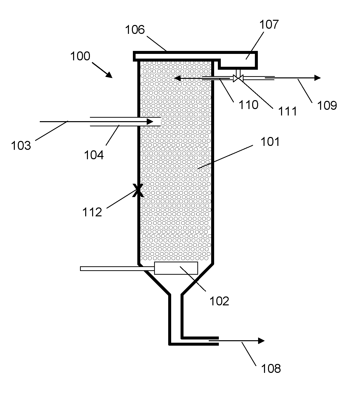
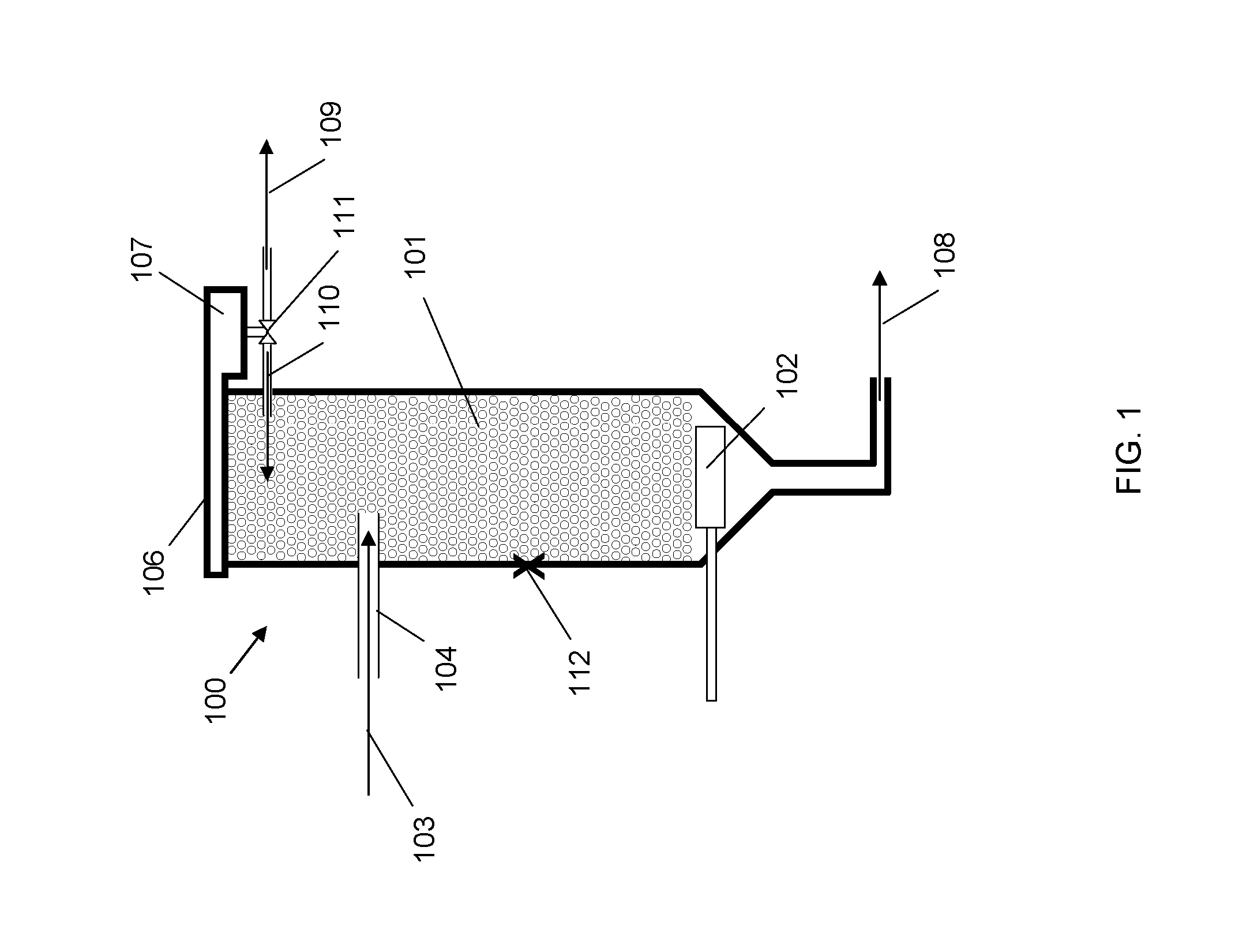
[0020]A feed stream comprised of particles of varying hydrophobicity is injected directly into the froth zone of a vertical flotation column. The injection of the feed stream into the froth zone results in the creation of bubble-particle attachments between a plurality of bubbles in the froth zone and the hydrophobic particles. Injection into the froth zone offers significant advantage because the interfacial bubble area per unit volume in the froth is very high, collision path lengths are short, and turbulence is low, leading to significantly higher particle collection rates. Additionally, the particles may adhere to several bubbles, making the method particularly effective for coarse particles, and recovery of smaller fines is increased as the fines become less likely to sweep around a bubble's streamlines in the more densely packed froth. This allows significantly higher feed rates for a given recovery and grade of concentrate stream as compared to a column relying on particle capture in a liquid collection zone, and elimination of the liquid collection zone greatly reduces the physical footprint of the vertical flotation column.
[0021]The method offers a means by which the poor selectivity typically experienced with direct froth injection methods is addressed, such that froth injection may be utilized for increased recovery while controlling the degree to which lower hydrophobicity particles are carried in the froth. As the froth moves upward through the froth zone, some of the bubble-particle aggregates experience detachment and enter the interstitial liquid. The detachment rate depends on the particle's strength of attachment and the presence of other mechanisms which encourage detachment, and is generally treated as inversely proportional to the hydrophobicity of the particle. Bubble coalescence in the froth may also occur, preferentially releasing lower hydrophobicity particles into the interstitial liquid.
[0022]The hydrophobic particles carried by the froth to froth overflow are transferred to a froth breaker where the bubbles comprising the froth in the froth overflow are intentionally disrupted, liberating the particles comprising the bubble-particle attachments and forming a slurry. A portion of the slurry is drawn off as a concentrate stream and the remaining portion of the slurry is returned to froth zone as a reflux stream. The introduction of the reflux stream improves the hydrophobic selectivity of the froth zone by increasing the concentration of the more hydrophobic particles in the interstitial liquid existing between the bubbles. This increases the likelihood that when less hydrophobic particles undergo detachment and enter the interstitial liquid, the more hydrophobic particles available in the interstitial liquid via the reflux stream will form bubble-particle attachments. The less hydrophobic particles are then increasingly likely to drain downward with the draining interstitial liquid and ultimately exit the vertical flotation column through the tailings stream. As a result, the grade of the product reporting to the froth overflow increases, and the grade of the slurry drawn off as the concentrate stream increases. Additionally, the reflux stream increases the downward flow of liquid through the froth zone to enhance draining action and further sweep unattached, less hydrophobic particles toward the tailings stream. This significantly reduces and can eliminate the wash-water requirements present in the conventional approach.
[0023]The 
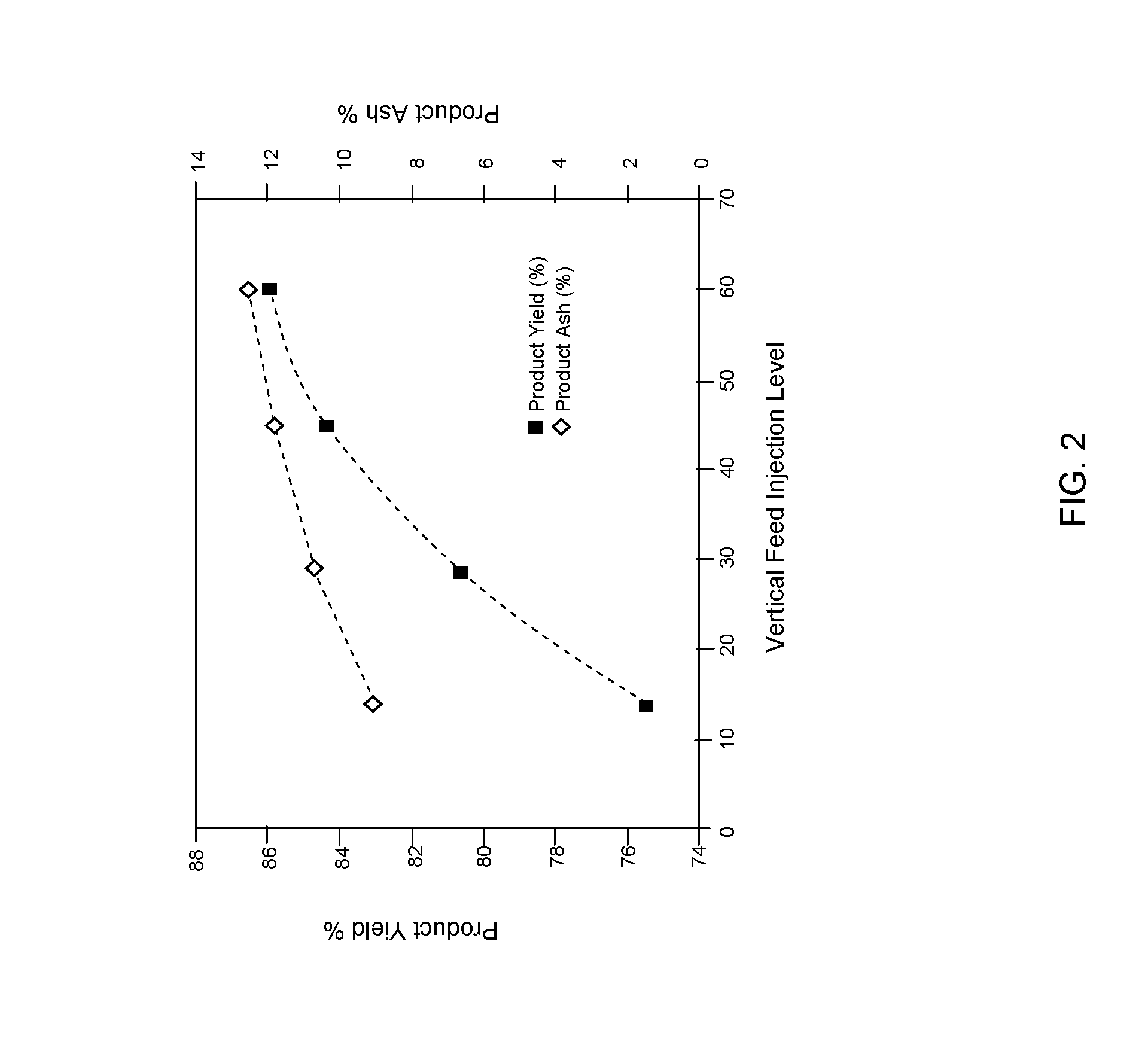
mass flow rate of the reflux stream may be varied in order to control the resulting grade of concentrate stream as operating conditions change. In addition, the vertical level of feed injection into the froth zone may be varied. An operating advantage of the method described herein is the ability to influence recovery and grade somewhat independently, by varying both the vertical level of feed stream and the magnitude of reflux stream, adding significant operational flexibility. Further, the method described substantially increases the maximum particle size typically recovered using conventional coal flotation. In conventional coal flotation, spiral circuits are typically utilized for recovery of particles having greater than 0.2 mm diameter. In an exemplary operation of this method using a coal slurry feed stream, a maximum particle size of +1.0 mm was recovered. Use of this method may therefore reduce the complexity of a plant by eliminating the need for spiral circuits.
[0024]The method thus provides particle separation by utilizing feed injection directly into the froth zone of a vertical flotation column combined with interstitial liquid displacement using reflux. The method facilitates removal of lower hydrophobicity particles from bubbles surfaces, offers simplified operational control, reduces or eliminates wash-water requirements, and reduces crushing and burdens by allowing capture of coarse particles beyond the upper limiting size for liquid injection columns, among other advantages. The method generally comprises: (1) generating a froth zone in a vertical flotation column having a vertical axis; (2) injecting the feed stream into the froth zone; (3) transferring and breaking froth overflow, producing a slurry; (3) injecting a reflux stream into the froth zone; (4) generating a concentrate stream and (5) generating a tailings stream.

Problems solved by technology

However, control of the process is difficult when the extent of bubble coalescence is a direct function of original separation column design, and the operating environment deviates significantly from the design environment.
This is a widely practiced and generally effective technique in industry, however the necessity for a continuous source of clean wash-water is a significant operational requirement.
Additionally, optimization can be difficult.
High water additions may also destabilize the froth by stripping surfactant from the surface of the bubbles, and may act to decrease product grade by increasing axial froth mixing, reducing wash-water effectiveness.
It may also produce excessively dilute column tailings products which are difficult to thicken.
The latter in particular places significant operational constraints on a separation process, as a bubble size too large relative to the hydrophobic particle results in the particle sweeping around the bubble, rather than colliding, and a bubble size too small relative to the hydrophobic particle may have insufficient buoyancy with which to carry the particle to the froth zone.
This directly impacts the crushing and grinding requirements prior to introduction of the particles into the separation column.
However, the main drawback to froth injection is the poor selectivity among particles of varying hydrophobicity.

Method used


Image

  • Method for enhancing selectivity and recovery in the fractional flotation of particles in a flotation column
  • Method for enhancing selectivity and recovery in the fractional flotation of particles in a flotation column
  • Method for enhancing selectivity and recovery in the fractional flotation of particles in a flotation column

Examples


Embodiment Construction

[0029]The following description is provided to enable any person skilled in the art to use the invention and sets forth the best mode contemplated by the inventor for carrying out the invention. Various modifications, however, will remain readily apparent to those skilled in the art, since the principles of the present invention are defined herein specifically to provide a method of particle separation using injection directly into the froth zone of a vertical flotation column coupled with interstitial liquid displacement using reflux, in a manner which facilitates removal of lower hydrophobicity particles from bubbles surfaces, offers simplified operational control, reduces or eliminates wash-water requirements, and reduces crushing and burdens by allowing capture of coarse particles beyond the upper limiting size for liquid injection columns.

Principles

[0030]Principles of the method may be illustrated with reference to FIG. 1. FIG. 1 shows a vertical flotation column 100 having a f...


PUM


Abstract

The method relates to particle separation from a feed stream. The feed stream is injected directly into the froth zone of a vertical flotation column in the presence of a counter-current reflux stream. A froth breaker generates a reflux stream and a concentrate stream, and the reflux stream is injected into the froth zone to mix with the interstitial liquid between bubbles in the froth zone. Counter-current flow between the plurality of bubbles and the interstitial liquid facilitates the attachment of higher hydrophobicity particles to bubble surfaces as lower hydrophobicity particles detach. The height of the feed stream injection and the reflux ratio may be varied in order to optimize the concentrate or tailing stream recoveries desired based on existing operating conditions.

Description

STATEMENT OF GOVERNMENTAL SUPPORT[0001]The United States Government has rights in this invention pursuant to the employer-employee relationship of the Government to the inventors as U.S. Department of Energy employees and site-support contractors at the National Energy Technology Laboratory.TECHNICAL FIELD[0002]A method of particle separation from a feed stream comprised of particles of varying hydrophobicity by injecting the feed stream directly into the froth zone of a vertical flotation column in the presence of a counter-current reflux stream. Bubble-particle attachments occur in the froth zone and froth overflow is transferred to a froth breaker. The froth breaker generates a reflux stream and a concentrate stream, and the reflux stream is injected into the froth zone of the vertical flotation column, such that the reflux stream mixes with the interstitial liquid between bubbles in the froth zone. A net flow of interstitial liquid flows in a downward direction providing a count...

Claims


Application Information

Patent Timeline
Patent Type & Authority Patents(United States)
IPC IPC(8): B03D1/02B03D1/24
CPCB03D1/24B03D1/1462B03D1/028
Inventor KLUNDER, EDGAR B.
Owner THE UNITED STATES AS REPRESENTED BY THE DEPARTMENT OF ENERGY
Why Eureka
Try Eureka