Fluorescent lamp with conductive coating

a technology of conductive coating and fluorescent lamps, which is applied in the manufacture of tubes/lamp screens, low-pressure discharge lamps, gas-filled discharge tubes, etc., can solve the problems of reducing lamp life, difficulty in passing an electric current from one electrode to the other, fluorescent lamps, etc., and achieves the effect of reducing the electrical impedance of the current path and reducing the open circuit voltag

Inactive Publication Date: 2008-05-27
GENERAL ELECTRIC CO
View PDF24 Cites 3 Cited by
  • Summary
  • Abstract
  • Description
  • Claims
  • Application Information

AI Technical Summary

Benefits of technology

[0017]According to a further aspect, the present invention concerns a fluorescent lamp that comprises a glass envelope having an exterior surface, a first electrode and a second electrode located within the glass envelope and a transparent electrically conductive material affixed to the exterior surface of the glass envelope. The transparent electrically conductive material extends between the vicinity of the first electrode and the vicinity of the second electrode and provides a path for an electric current to pass between the first electrode and the second electrode so as to reduce the open circuit voltage required to start the fluorescent lamp. Since the path length for the electric current flow through a gaseous medium during ignition of the lamp for a lamp without a starting aid is the distance between the electrodes, the electrically conductive material provides a shorter path length. In the latter instance, the length of the path is the distance between the first electrode and its adjacent walls plus the distance between the second electrode and its adjacent walls. Additionally, the electrical current path through the transparent electrically conductive material has a very low impedance so as to reduce the open circuit voltage required to start the fluorescent lamp. According to a particular aspect, the impedance of the current path through the transparent electrically conductive material is controlled so as to fall below a specified value in order to reduce the open circuit voltage required to start the fluorescent lamp to a target level of approximately 300 volts or less.
[0022]According to yet another aspect, the at least one stripe of the transparent electrically conductive material comprises a first layer of the transparent electrically conductive material in engagement with the exterior surface of the glass envelope and one or more layers of transparent electrically conductive material that can be superimposed on top of the first layer of the transparent electrically conductive material. Alternatively, the additional layers can be applied adjacent the first layer of the electrically conductive material or elsewhere on the exterior of the glass envelope in order to further reduce the electrical impedance of the current path through the plurality of stripes and layers in order to reduce the open circuit voltage required to start the fluorescent lamp below about 300 volts or some other desired voltage level.

Problems solved by technology

Consequently, it is difficult to pass an electric current from one electrode to the other and establish an electric arc between the electrodes capable of sustaining the generation of white light within the glass envelope.
The electrons required by the electric arc during ignition and briefly thereafter are primarily emitted from the electrodes by a damaging process of secondary electron emission.
The high energy ions not only eject electrons from the cold electrodes but they also sputter the emission mix and the tungsten metal from the electrodes, typically resulting in reduced lamp life.
There can be instances where fluorescent lamps, for various reasons, are difficult to start or transition to arc.
For example, the ballast available in a particular instance may not be capable of generating an open circuit voltage that exceeds the ignition voltage required for the lamp to ignite.
However, if the watt-miser fluorescent lamps are paired with the rapid-start or programmed-start ballasts described above, that are only capable of providing open circuit voltages of less than 400 volts, (but which typically provide for longer lamp life) the watt-miser fluorescent lamps may not ignite.
A disadvantage with this starting aid is that the metal strip covers a relatively large percentage (approximately five percent) of the exterior surface of the glass envelope.
Another disadvantage is that the metal strip is visible at significant distances.
A further disadvantage arises because the strip is usually manually attached to the lamp with an adhesive and an insulating cover to protect against electric shock.
This manual process significantly increases the costs of manufacture.
As with the opaque metal strip referred to above, a disadvantage with this starting aid is that it absorbs an important quantity (more than approximately one to two percent) of light emitted by the lamp.
Another disadvantage is that the tin oxide coating creates potential concerns related to safety and lamp breakage during the manufacturing process.
A further disadvantage from an environmental standpoint is that a corrosive agent is required to be used during the coating of the glass envelopes.
However, the proximity of the luminaire to the lamp electrodes is important in that case and the greater the separation, the less efficient is the starting aid.

Method used


Image

  • Fluorescent lamp with conductive coating
  • Fluorescent lamp with conductive coating
  • Fluorescent lamp with conductive coating

Examples


Embodiment Construction

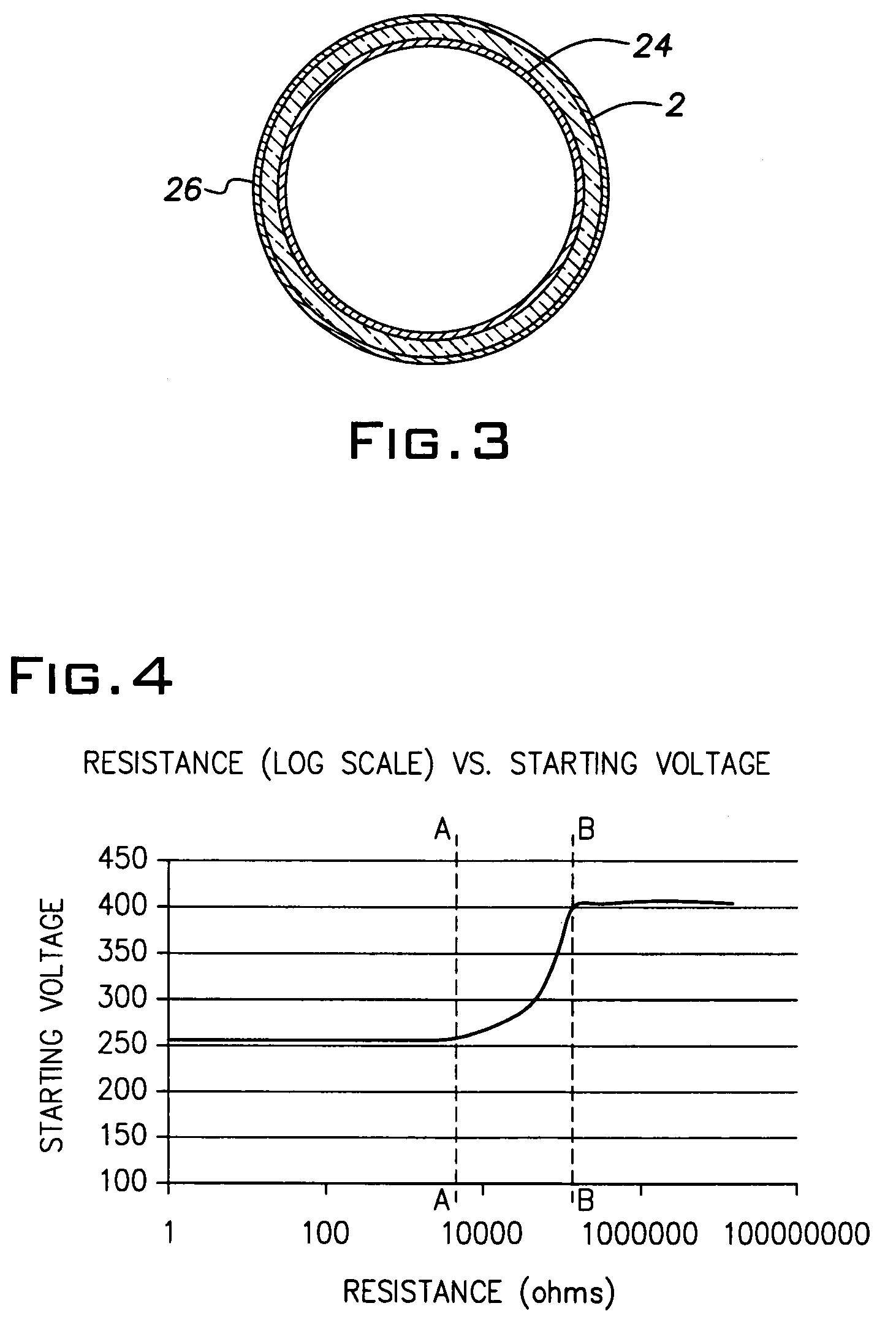
[0029]In the description that follows, reference is made to the electrically conductive materials of the invention as comprising transparent electrically conductive materials. The word transparent is not used herein in a limited sense to mean that the electrically conductive materials are capable of transmitting light as if the electrically conductive material were not present, although the invention is broad enough to cover electrically conductive materials of that kind. Rather, the word transparent is used in the more general sense to indicate that the materials are capable of transmitting light to a significant degree such as would be the case, for example, when the transparent electrically conductive material absorbs less than approximately one to two percent of the light emitted by the fluorescent lamp as mentioned in paragraphs [0013] and [0014] above.

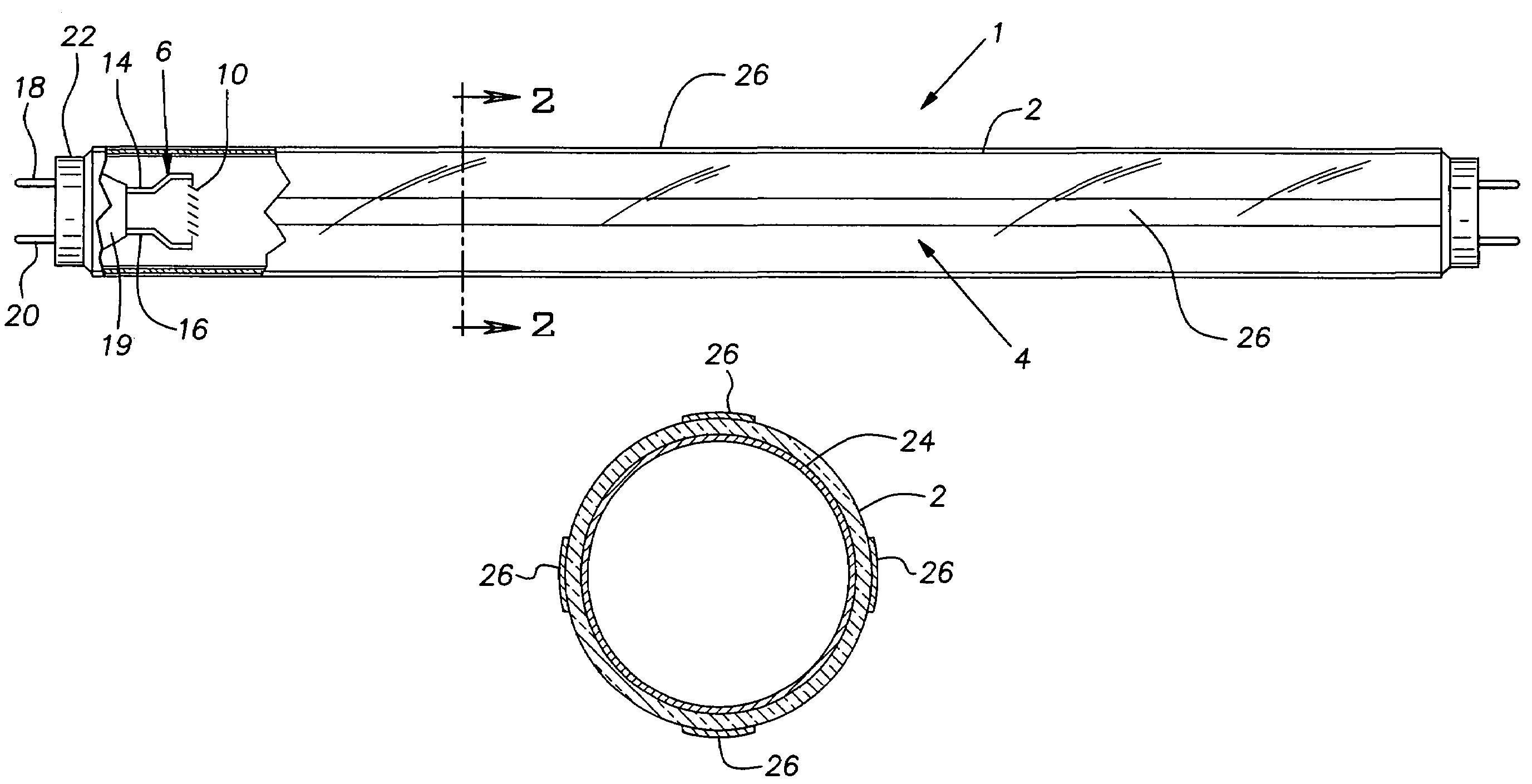
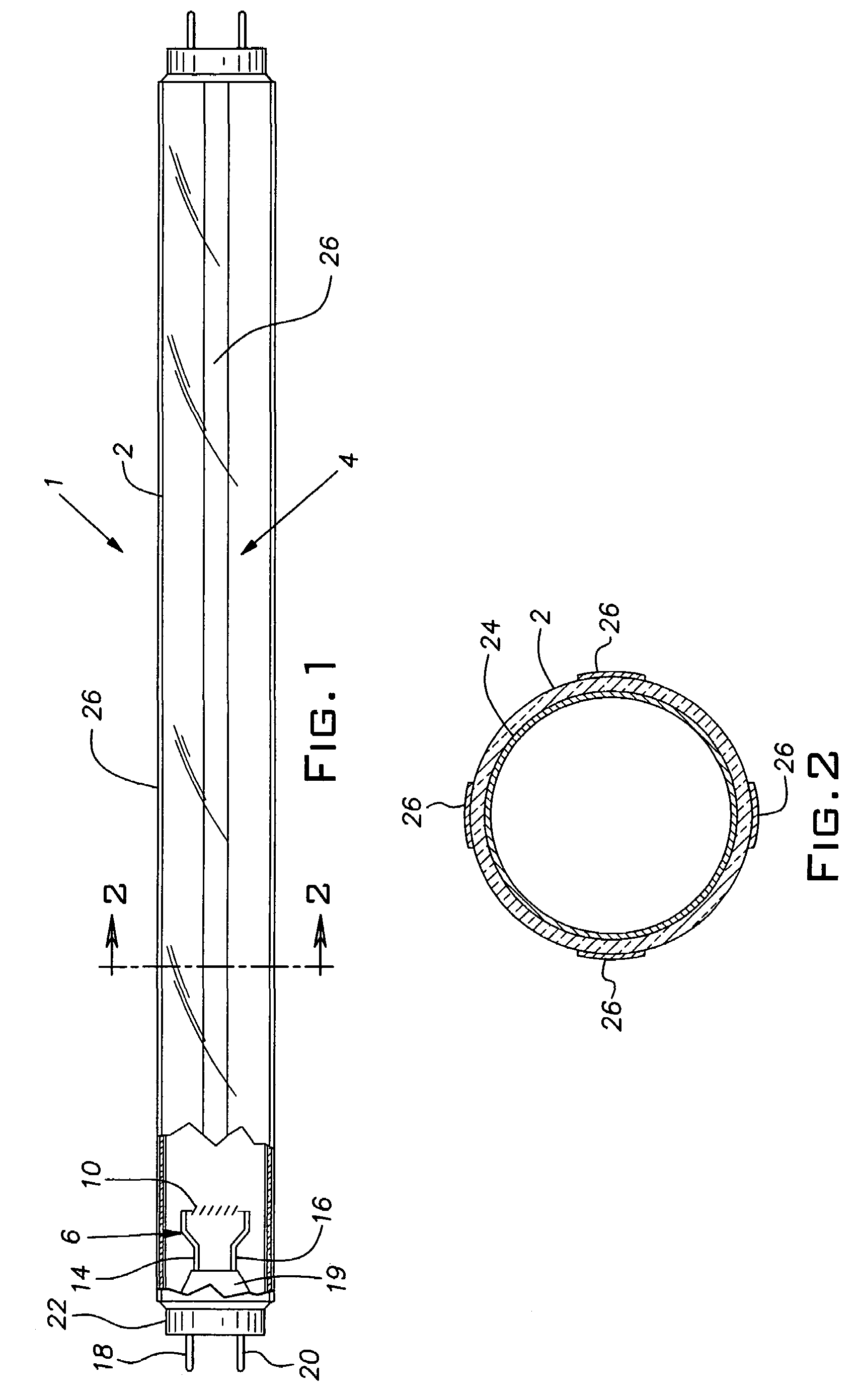
[0030]As noted above, according to one aspect, the present invention concerns a fluorescent lamp that comprises a glass envelop...


PUM


Abstract

Fluorescent lamps that comprise a glass envelope with an exterior surface and first and second electrodes located within the glass envelope include a transparent electrically conductive material affixed to the exterior surface of the glass envelope. The transparent electrically conductive material extends between the vicinity of the first electrode and the vicinity of the second electrode, thereby providing a path for an electric current to pass between the first and second electrodes and reduce the open circuit voltage required to start the fluorescent lamp. The transparent electrically conductive material affixed to the exterior surface of the glass envelope can comprise one or more stripes of the material so that less than the total exterior surface area of the glass envelope is covered by the transparent electrically conductive material.

Description

BACKGROUND OF THE INVENTION[0001]The present invention relates in general to fluorescent lamps and in particular to fluorescent lamps the glass envelopes of which include a transparent electrically conductive material that serves to reduce the open circuit voltage required to start the fluorescent lamps.[0002]The operation of fluorescent lamps is well understood by those skilled in the art, but certain salient features of the operation are reviewed here for the purposes of facilitating a better appreciation of the benefits of the present invention.[0003]A fluorescent lamp typically comprises a sealed glass envelope, usually in the form of a glass tube, that contains a small amount of mercury and an inert gas under low pressure. Examples of inert gases that can be used are argon, krypton, neon, xenon and mixtures thereof. The inside surface of the glass envelope is coated with a phosphor powder. Two electrodes are located within the glass envelope and are wired to an electric circuit...

Claims


Application Information

Patent Timeline
Patent Type & Authority Patents(United States)
IPC IPC(8): H01J11/00
CPCH01J9/20H01J61/35H01J61/547H01J61/72
Inventor KARRS, EVANBEERS, WILLIAM W.PIERCE, MATTHEWALLEN, GARY R.
Owner GENERAL ELECTRIC CO
Why Eureka
Try Eureka