Method of continuously producing flat glass by rolling

a technology of flat glass and rolling glass, which is applied in the direction of glass transportation equipment, glass making equipment, glass shaping equipment, etc., can solve the problems of high investment cost high maintenance costs, and high risk of affecting the quality of float glass plants, so as to reduce operating costs, improve surface quality, and reduce surface defects

Inactive Publication Date: 2011-05-03
SCHOTT AG
View PDF20 Cites 4 Cited by
  • Summary
  • Abstract
  • Description
  • Claims
  • Application Information

AI Technical Summary

Benefits of technology

[0012]It is an object of the present invention to provide a method for continuously producing flat glass by rolling, in which glass may be produced largely without damage to its surface, which is easily controllable and which largely maintains the current comparatively short cooling path length provided by conventional rolling methods.
[0018]The width of the linear contact area should be dimensioned so that forces for slippage-free transport of the glass sheet can be transmitted from the shaping roller to the glass sheet. Generally this is successful when the width of the linear contact area is from 0.5 to 3 cm. The required width depends, among other things, on the viscosity and the speed (m min−1) of the glass sheet. Higher speeds and lower viscosities result in wider contact area; higher glass viscosities and lower drawing speeds require smaller contact areas with a constant steam throughput rate. The width of the contact zone influences the cooling efficiency of the rollers. The wider is the contact zone, the better the cooling of the glass sheet.
[0022]Water is the most economical means for producing a gas pressure, since water vapor or steam does not react with glass and is not toxic.
[0025]The open-pored material, which is used to make at least a part of the roller, is preferably sintered metal or porous ceramic. The rapidity of the evaporation process and the intensity of the heat exchange may be regulated to a certain extent by the properties of the open-pored material. A lower thermal diffusion number a=λ / cγ and a high porosity (e.g. about 30 to 40%) makes the vapor or gas formation easier and leads to a lower heat flow density between the glass and the open-pored material (e.g. about 10 to 20×103 W / m2) while a high thermal diffusion number (e.g. in the case of bronze as the sintered material) and a low porosity (e.g. in the range of about 5 to 10%) delays evaporation and increases the heat exchanged (obtained heat flow density e.g. in a range between about 50 to 100×103 W / m2). A delay of the evaporation and a resulting increase in heat exchange may result and above all cause a correspondingly high pressure to be used (e.g. 0.5 MPa and above).
[0028]The rollers can be constructed asymmetric with a larger pore structure in the interior and a finer pore structure on their side facing the glass. In this case the fine-pore structure has a pore size range according to the individual application of from 0.5 to 10 μm (d50-value), while the large-pore structure with a pore size between 2 and 100 μm (d50 value) provides mechanical stability. One such asymmetric structure has the advantage that the flow resistance is less than a roller entirely consisting of fine-pored material, which leads to a lowering of the operating costs, so that the fine-pored section can be made of a more expensive material than the large-pored supporting section that supports it. Also the fine-pored section naturally causes less surface defects when it contacts the glass. A pore size of from 0.5 to 10 μm (d50-value) is preferred at least for the roller coming in contact with the glass sheet.
[0029]Furthermore it is also possible to vary the porosity of the roller coming in contact with the glass sheet axially so that a discontinuous linear contact area is formed, which extends over the entire roller width. If a reduced pressure is used only in the edge region of the roller, contact between the roller and the glass sheet occurs in the edge region of the glass sheet, while the region of the glass sheet between the edges has no contact with the roller and thus an improved surface quality. If the width of the contact region is selected so that the forces required for the sheet transport are still transmitted from the roller to the glass sheet, one can produce a special flat glass with an especially higher surface quality. Generally it is sufficient for this purpose when the linear contact area corresponds to about 2 to 5% of the usable roller width.

Problems solved by technology

However it also has the disadvantages that the investment costs for a float glass plant are very high and that one side of the float glass produced is contaminated with tin ions from the float bath, which is troublesome in many applications.
Furthermore among other disadvantages these methods were susceptible to maintenance problems and sensitive to disturbance of the glass composition and temperature guidance and control in the drawing chamber.
The apparatus for performing the method is simple, but has the disadvantage that the resulting glass surface has an image or imprint, which more or less matches the shape of the surfaces of the shaping rollers.
This generally damages the surface quality, but it can be desired as in ornamental glass manufacture.
The surface temperature of the shaping roller cannot be freely selected.
A surface temperature that is too high leads to adherence of the glass on the roller.
However a surface temperature that is too low leads to too strong cooling of the glass and to breakage of the glass between the shaping rollers.
On the other hand insufficient cooling leads to a too soft sheet and has a negative effect on the dimensional stability of the flat glass, especially its thickness.
Thus the plant performance (flat glass throughput) has an upper limit determined by the cooling power realized under these conditions.
However the circumstance that the gas and vapor in this method have a clearly poorer thermal conductivity than metallic or ceramic roller material is disadvantageous.
Also a longer cooling path must be selected, which is not always easy and is associated with contingent rebuilding of the existing apparatus and in each case with higher costs.
Above all, it is not always possible to control the frequently occurring slipping, Which impairs the operation of the plant and because of that can lead to quality problems.

Method used


Image

  • Method of continuously producing flat glass by rolling
  • Method of continuously producing flat glass by rolling

Examples


example

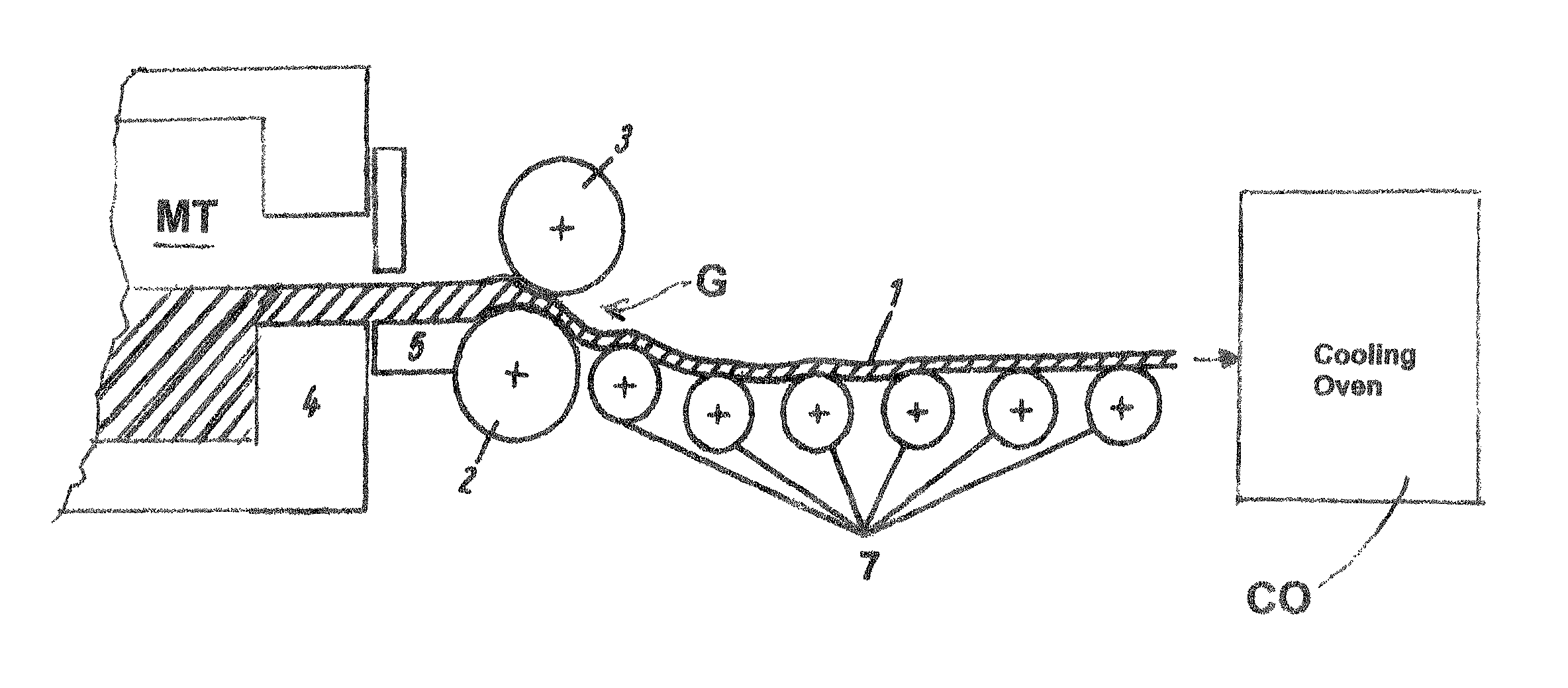
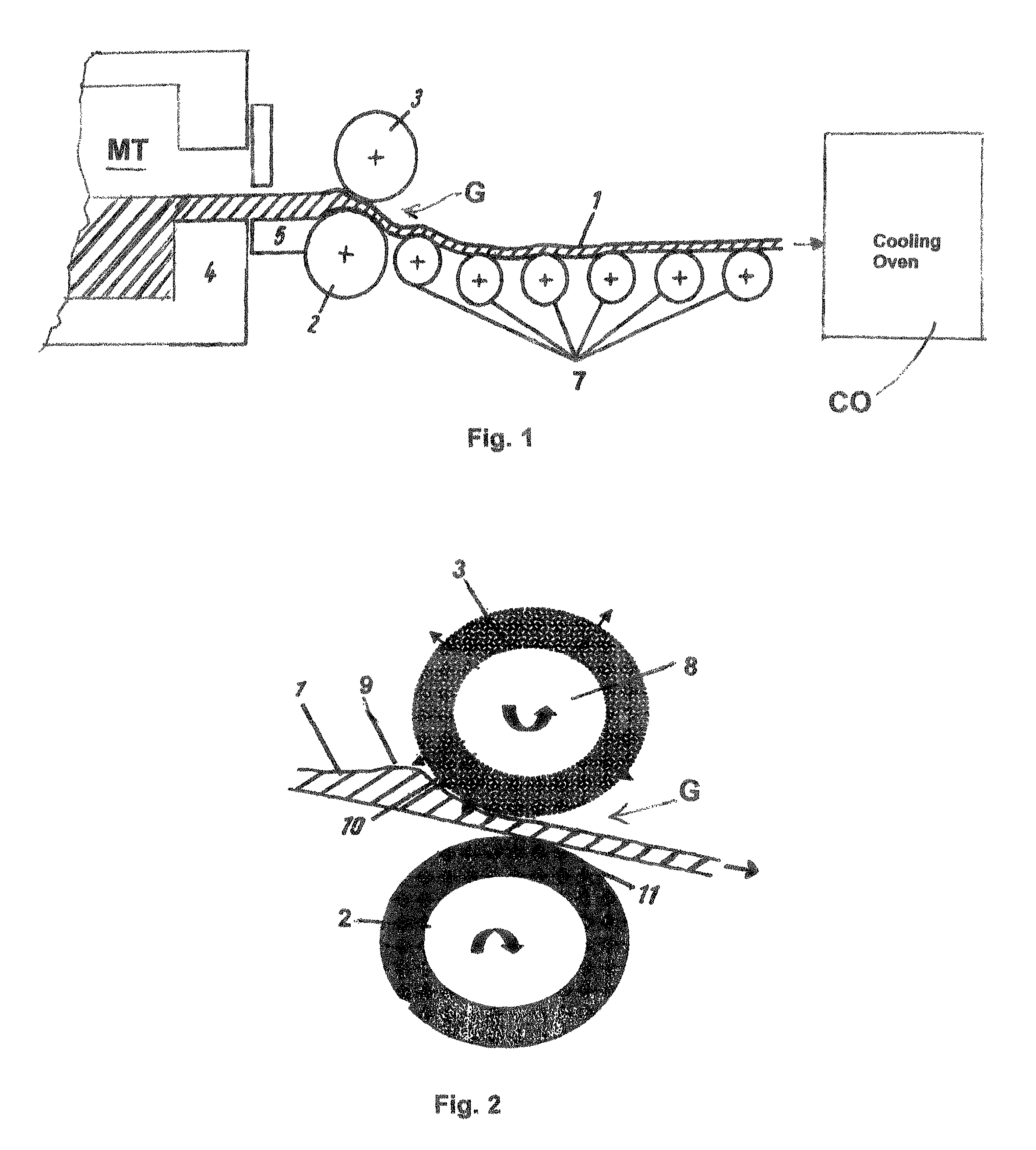
[0036]A glass flow coming from a glass melt tank at a temperature of about 1400° C. was rolled between two shaping rollers 2, 3 with a diameter of 160 mm, which rotate a 4 rpm. The rollers had a spacing of 4 mm from each other. The upper shaping roller comprises a hollow cylinder with a porous cylindrical jacket having a thickness of 45 mm, a porosity of 50% and permeability for water of 1×10⁻¹³ m2. The upper shaping roller was acted on with distilled water under a pressure of 250 kPa. The lower shaping roller was constructed in the same manner. In operation the temperature of the roller surfaces was about 400° C. to 450° C. A gas cushion of less than or equal to 0.1 mm formed between the upper roller and the glass sheet by steam vaporized in the pores of the upper shaping roller. The pressure was adjusted in the lower shaping roller so that a contact zone of a 5 to 30 mm width resulted between the lower shaping roller and the glass sheet. The surface quality of the upper surface of...


PUM

PropertyMeasurementUnit
widthaaaaaaaaaa
widthaaaaaaaaaa
thicknessaaaaaaaaaa

Abstract

The method of continuously producing flat glass includes rolling a fluid glass sheet between upper and lower shaping rollers to shape and calibrate the glass sheet, generating a respective gas cushion between the fluid glass sheet and each shaping roller from a liquid, controlling the pressure of the gas cushion between the fluid glass sheet and the upper shaping roller to completely prevent contact of the glass sheet with the upper shaping roller, controlling the pressure of the gas cushion between the fluid glass sheet and the lower shaping roller to form a linear contact area between the fluid glass sheet and the lower shaping roller and controlling the contact area width according to speed and viscosity of the glass sheet in order to transport it without slipping and reduce cooling path length.

Description

BACKGROUND OF THE INVENTION[0001]1. The Field of the Invention[0002]The present invention relates to a method of continuously producing flat glass, such as sheet glass or window glass, by rolling, in which a fluid glass sheet is molded or shaped in a forming zone between at least two porous shaping rollers and conveyed by means of conveying rollers from the forming zone.[0003]2. Related Art[0004]The float glass process has the greatest versatility from among the many different methods of flat glass production, since the flat glass produced with that process has an excellent surface quality. However it also has the disadvantages that the investment costs for a float glass plant are very high and that one side of the float glass produced is contaminated with tin ions from the float bath, which is troublesome in many applications.[0005]The glass quality, which was achievable by means of the float process, was not achieved by the drawing process, which was developed during the first qua...

Claims


Application Information

Patent Timeline
Patent Type & Authority Patents(United States)
IPC IPC(8): C03B13/00C03B13/04C03B13/08C03B13/16C03B23/033
CPCC03B13/04C03B40/04C03B35/188C03B13/16
Inventor GREULICH-HICKMANN, NORBERTLANGSDORF, ANDREASLANGE, ULRICHSCHROEDER, FRITZ
Owner SCHOTT AG
Why Eureka
Try Eureka