Vehicle occupant protection apparatus

a technology for protecting equipment and vehicles, applied in the direction of vehicular safety arrangements, pedestrian/occupant safety arrangements, vehicular components, etc., can solve the problems of increasing cost and weight, and achieve the effect of enhancing the ability to protect the vehicle occupants, and reducing the strength of the forward and rear attachment points

Inactive Publication Date: 2007-06-21
HONDA MOTOR CO LTD
View PDF10 Cites 31 Cited by
  • Summary
  • Abstract
  • Description
  • Claims
  • Application Information

AI Technical Summary

Benefits of technology

[0026] The lower portion of the expansion part will thus be extended in the longitudinal direction of the vehicle body and, by remaining in contact with the vehicle body, will not slacken from the vehicle cabin to the outer side. The entirety of the expansion part therefore exhibits an ability to provide substantially uniform protection for the vehicle occupants. As a result, the vehicle occupant protection apparatus has an enhanced ability to protect the vehicle occupants.
[0027] Since the expansion part does not slacken from the vehicle cabin to the outer side, the tensile force needed for the expansion part to

Problems solved by technology

However, the inflator 251 will be larger, which becomes a primary factor i

Method used


Image

  • Vehicle occupant protection apparatus
  • Vehicle occupant protection apparatus
  • Vehicle occupant protection apparatus

Examples


first embodiment

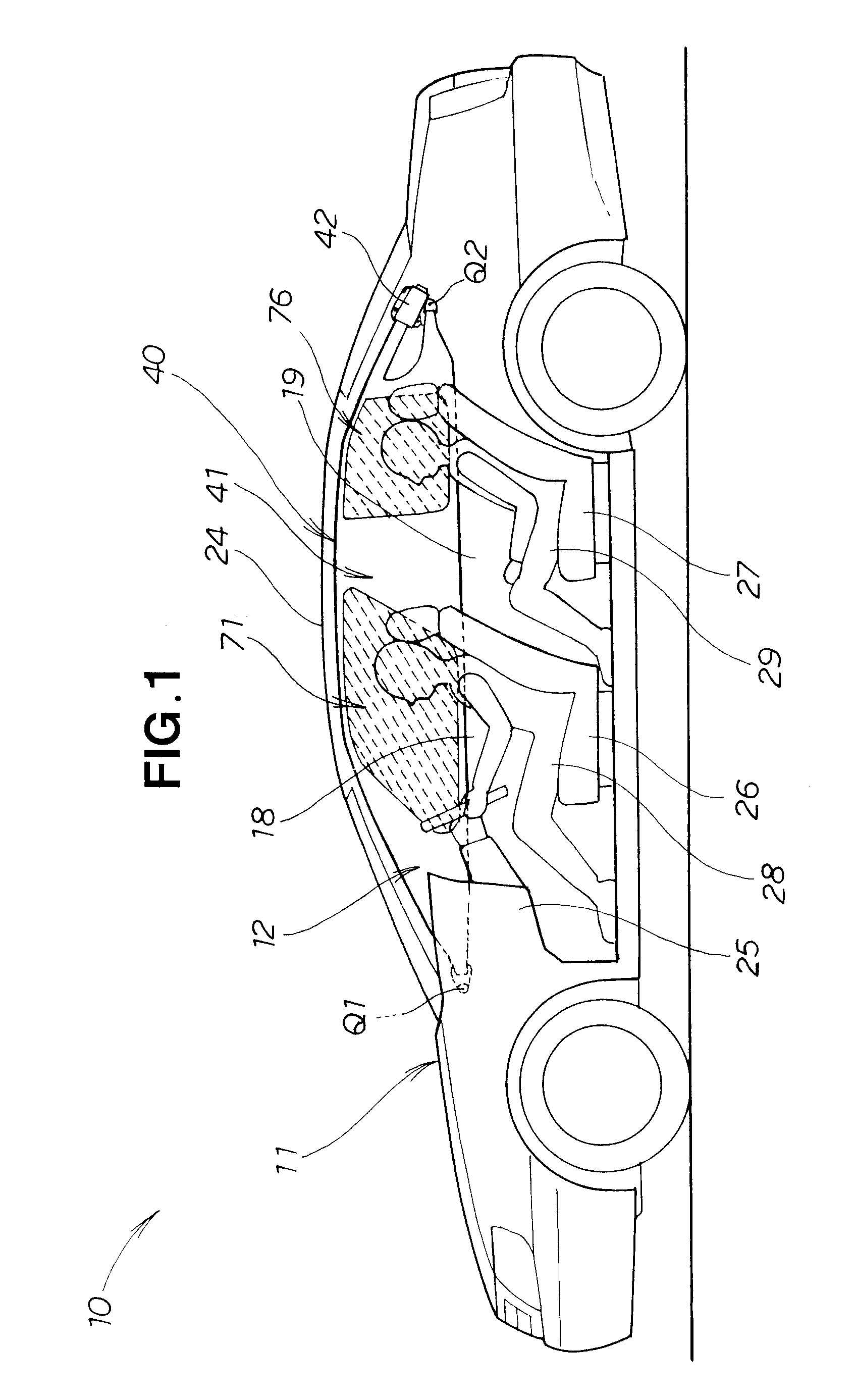
[0070] A vehicle occupant protection apparatus will first be described based on FIGS. 1 through 5.

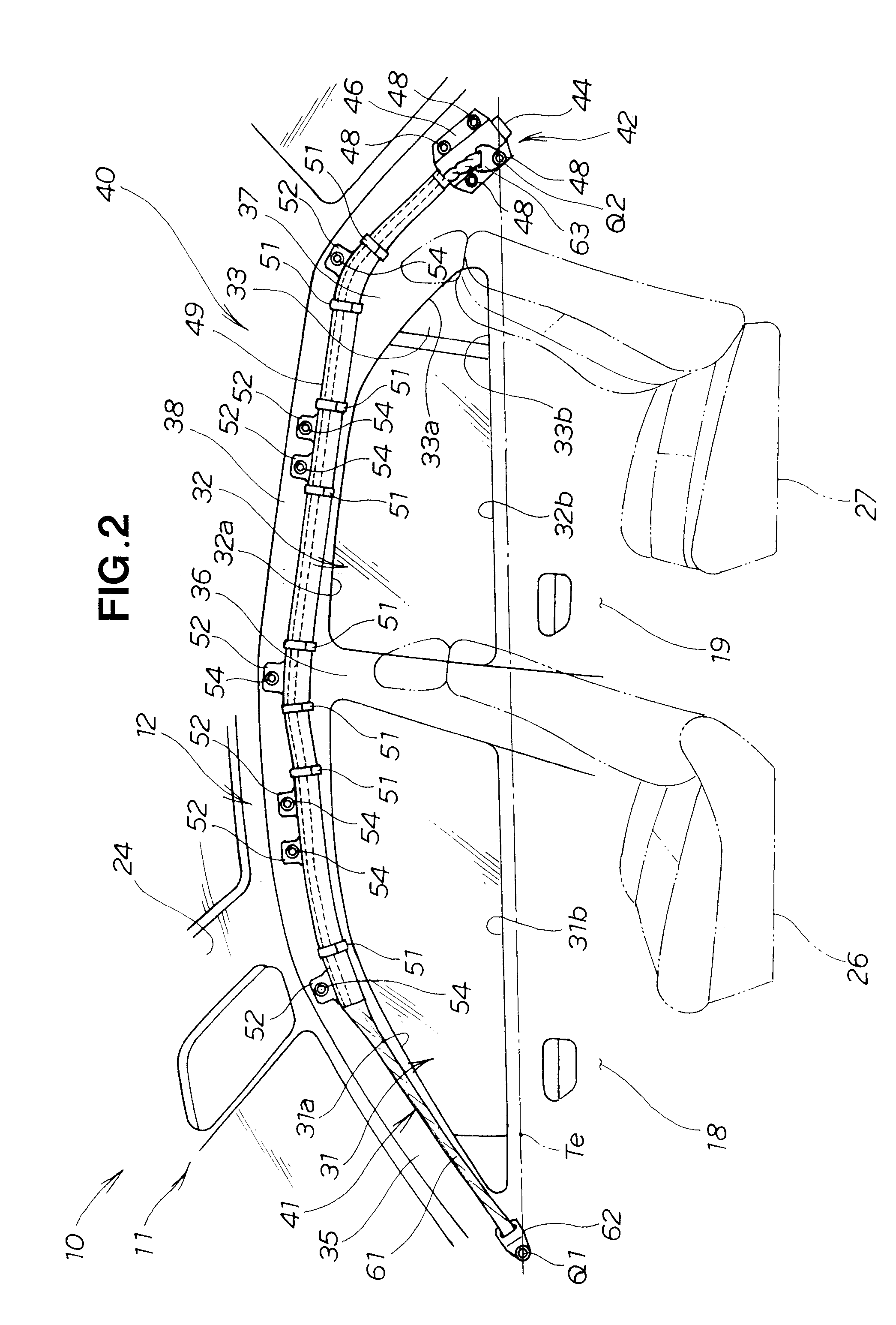
[0071]FIG. 1 shows a vehicle 10 equipped with a vehicle occupant protection apparatus 40 according to the first embodiment. As shown in FIGS. 1 and 2, the vehicle 10 has a monocoque vehicle body 11 and is provided with two seats 26, 27, i.e., a front seat 26 and a back seat 27, in the front and rear of a vehicle cabin 12. The front seat 26 is the sitting location for a driver or other vehicle occupant 28, and the back seat 27 is the sitting location for a vehicle occupant 29.

[0072] The vehicle body 11 has a front pillar 35 in the forward portion, a center pillar 36 in the middle portion, a rear pillar 37 in the back portion, and a roof side-rail 38 that joins the upper ends of each pillar 35, 36, 37. The roof side-rail 38 supports a roof 24 and is an elongated member running lengthwise along the vehicle body 11. In other words, the roof side-rail 38 is provided along the side edge of ...

second embodiment

[0135] Next, an operation of the vehicle occupant protection apparatus 40A will be described.

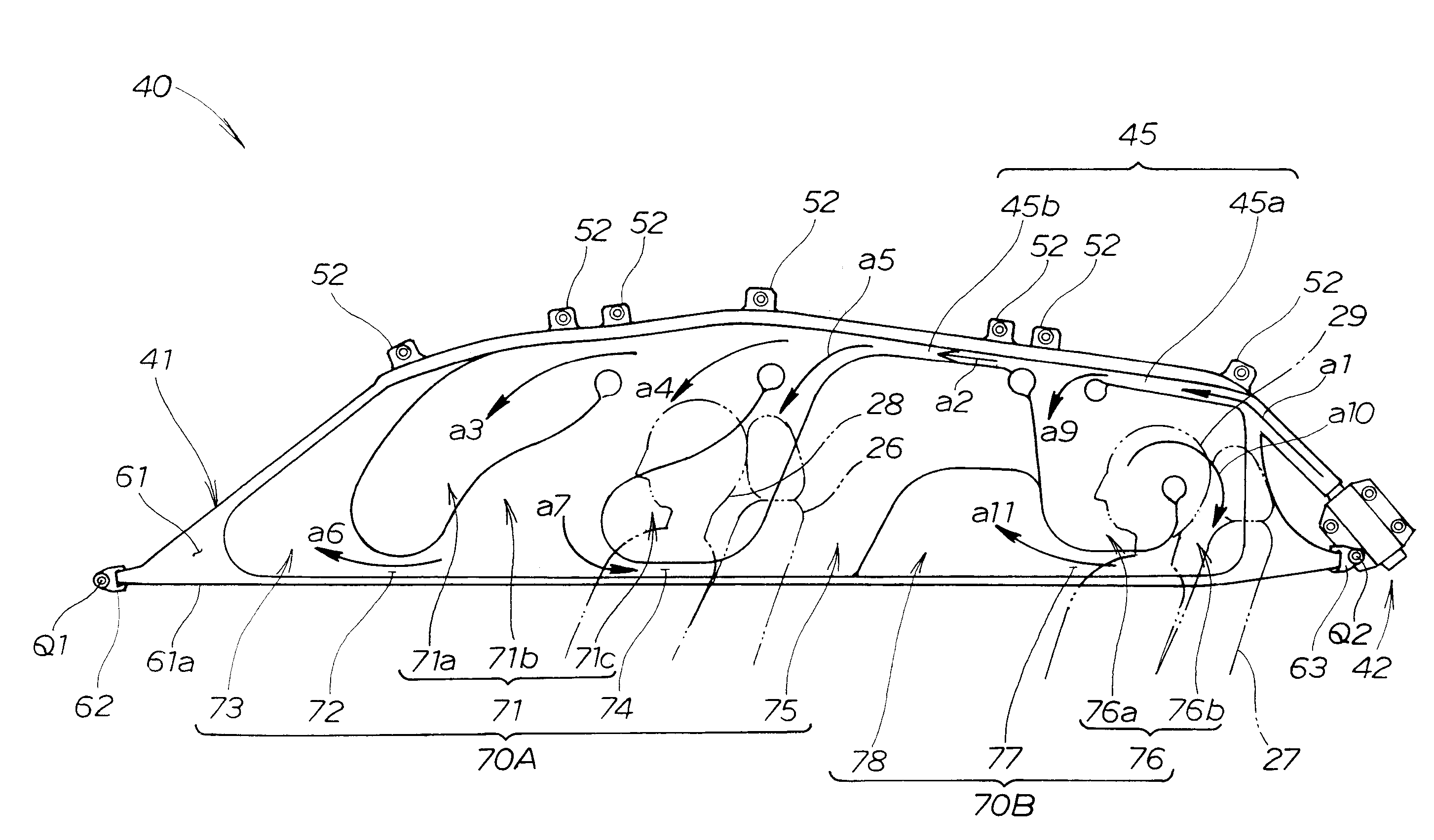
[0136] As shown in FIGS. 6 and 9, the forward communicating channel 72, which connects the first occupant-protecting inflation part 71 and the first internal-pressure-regulating inflation part 73, has a reduced diameter. Therefore, the flow rate of gas flowing from the first occupant-protecting inflation part 71 and into the first internal-pressure-regulating inflation part 73 is smaller than the flow rate of gas fed into the first occupant-protecting inflation part 71. When gas is fed to the first occupant-protecting inflation part 71 and the internal pressure thereof suddenly increases, the pressure necessary to protect vehicle occupants is attained. Although the first occupant-protecting inflation part 71 is in constant connection to the first internal-pressure-regulating inflation part 73, little time elapses from when the first occupant-protecting inflation part 71 begins to inflate un...

third embodiment

[0192] Next, a first modification of the vehicle occupant protection apparatus will be described based on FIGS. 16A, 16B, and 17. FIGS. 16A and 16B schematically show the cross-sectional structure of the principal components of the vehicle 10 viewed from the rear. FIG. 17 schematically shows a vehicle occupant protection apparatus 40C viewed from the rear as in FIG. 16A.

[0193] As shown in FIGS. 16A and 17, the vehicle occupant protection apparatus 40C of the first modification has the secondary inflation parts 82, 84 positioned on the stored side curtain airbag 41. The configuration is otherwise the same as the configuration of the third embodiment shown in the above-mentioned FIGS. 13 through 15.

[0194] The secondary inflation parts 82, 84 are stored in a folded state on a surface 70a of the primary inflation parts 70A, 70B on the side of the vehicle cabin 12. The communication channels 81, 83 are located at the folding points of the secondary inflation parts 82, 84 relative to th...


PUM


Abstract

A vehicle occupant protection apparatus for use in a vehicle includes an occupant-protecting expansion part caused to expand in the form of a curtain in the vehicle cabin along windows. The expansion part is attached to the vehicle body at two attachment points positioned forward and rearward of the windows. A tension line that joins the two attachment points is in a position where the expansion part is extended between the two points, and is positioned below the lower edges of the windows.

Description

FIELD OF THE INVENTION [0001] The present invention relates to a vehicle occupant protection apparatus made to cover a window by causing an occupant-protecting expansion part to expand in the form of a curtain on a side of a vehicle cabin when the side of the vehicle is subjected to a force of impact. BACKGROUND OF THE INVENTION [0002] One type of vehicle occupant protection apparatus specifically increases the ability to protect the heads of the vehicle occupants when a side of the vehicle is subjected to an impact force from the outside. In this vehicle occupant protection apparatus, a folded expansion part is positioned in a location stretching from the roof of the vehicle to an upper edge of a window. The expansion part is a member capable of mitigating impact force. Side curtain airbag apparatuses are a well-known example of this type of vehicle occupant protection apparatus. [0003] With side curtain airbag apparatuses, a side curtain airbag expands along windows, and specific ...

Claims


Application Information

Patent Timeline
IPC IPC(8): B60R21/213B60R21/23B60R21/232
CPCB60R21/232
Inventor TAKEMURA, NAOKIIKEDA, KOJIHIRAYAMA, HIROYUKINAKAMURA, TAKASHIISAYAMA, HIROYUKI
Owner HONDA MOTOR CO LTD
Why Eureka
Try Eureka