Image display apparatus

a technology of image display and display device, which is applied in the direction of lighting apparatus, light sources, instruments, etc., can solve the problems of reduced leds, degraded brightness, and increased temperature and achieve the effect of reducing the temperature increase of light emitting elements

Inactive Publication Date: 2007-06-21
SAMSUNG ELECTRONICS CO LTD
View PDF3 Cites 22 Cited by
  • Summary
  • Abstract
  • Description
  • Claims
  • Application Information

AI Technical Summary

Benefits of technology

[0014]Since the light-up controller divides the n light emitting elements having at least one wavelength into m light-up groups having the same light-up timing, and the m ligh...

Problems solved by technology

However, when a multi-chip LED light source unit is used to make a small sized device, the plurality of LED chips are adjacent to one another, and thus, the temperature increases during the light-up time.
As a result, the lifespan of the LEDs may be reduced or the brightness thereof may be degraded.
Although a device for periodically switching on and off a plurality of LEDs is described in the aforementioned related art Japanese Paten...

Method used


Image

  • Image display apparatus
  • Image display apparatus
  • Image display apparatus

Examples


Embodiment Construction

[0023]Hereinafter, exemplary embodiments will be described with reference to the accompanying drawings. Like reference numerals denote like or similar elements throughout the drawings.

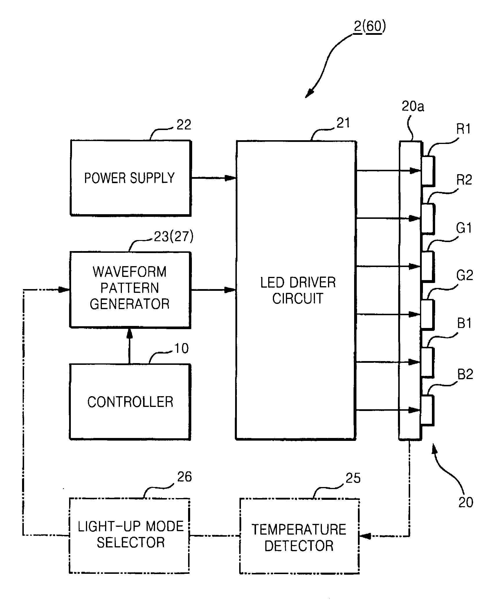
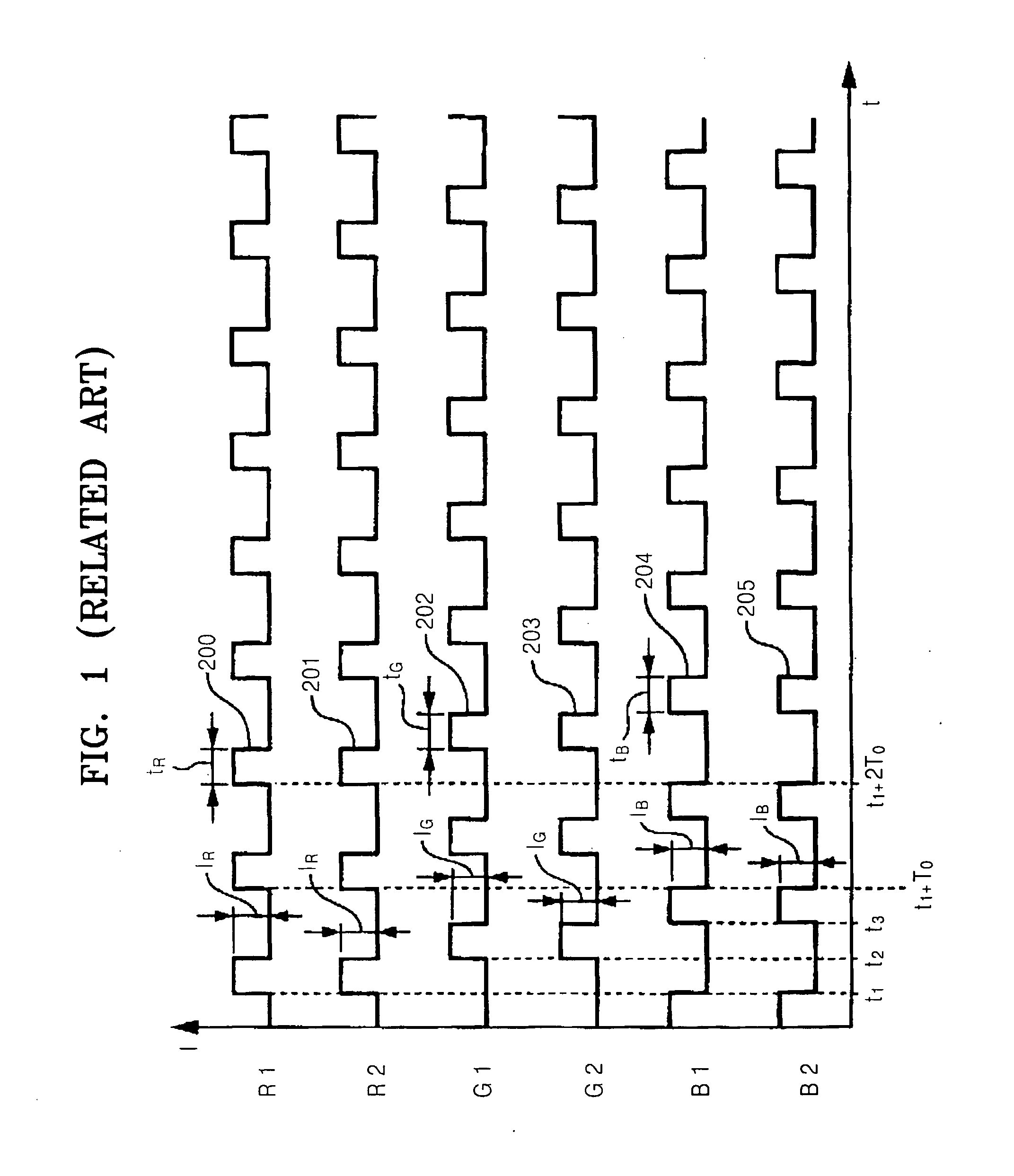
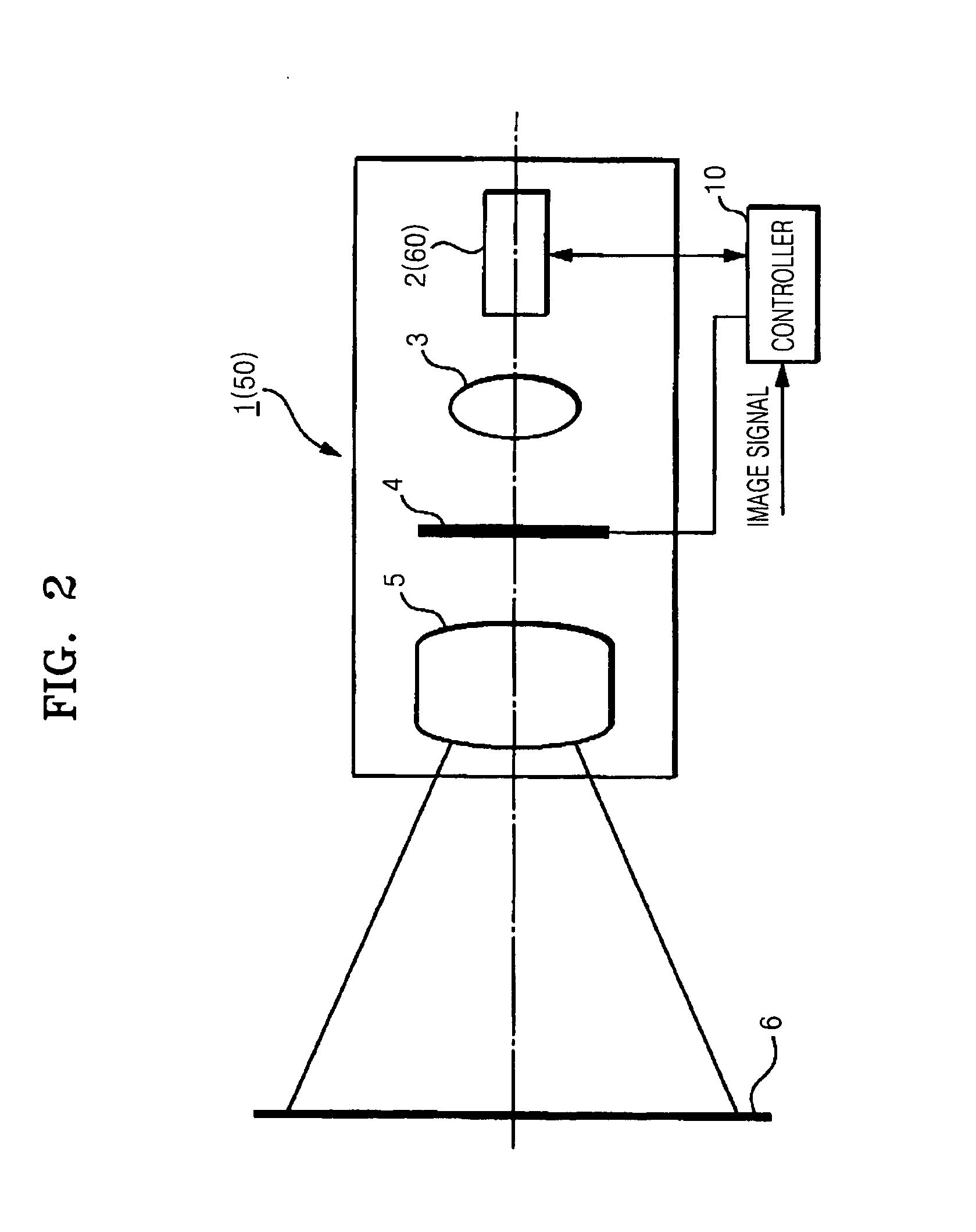
[0024]FIG. 2 is a schematic view illustrating a configuration of an image display apparatus 1 according to an exemplary embodiment of the present invention. FIG. 3 is a block diagram illustrating a configuration of a light source unit and a light controller used in the image display apparatus 1, according to an exemplary embodiment of the present invention. FIG. 4 is a timing chart illustrating a driving signal of a light source unit, wherein the driving signal is generated by a light controller of the image display apparatus 1, according to an exemplary embodiment of the present invention.

[0025]The image display apparatus 1 is a projector which projects a full color image onto a reflective screen 6 in response to an external signal. The image display apparatus 1 includes an illumination unit 2, a cond...


PUM


Abstract

An image display apparatus includes a light source unit including light emitting elements halving different wavelengths, wherein n (n is an integer higher that 2) light emitting elements have at least one wavelength; and a light-up controller which drives the light emitting elements having different wavelengths in a time-sequential manner within a time period, wherein the light-up controller divides the n light emitting elements having at least one wavelength into m (m is an integer satisfying 2≦m≦n) light-up groups having a same light-up timing, and the m light-up groups are alternately lighted at a frequency of 1/m within the time period, so that any one of the m light-up groups can be lighted within the time period.

Description

CROSS-REFERENCE TO RELATED PATENT APPLICATION[0001]This application claims priority from Japanese Patent Application No. 10-2005-0368039, filed on Dec. 21, 2005 in the Japanese Intellectual Property Office, and Korean Patent Application No. 10-2006-0094336, filed on Sep. 27, 2006 in the Korean Intellectual Property Office, the disclosures of which are incorporated herein in their entirety by reference.BACKGROUND OF THE INVENTION[0002]1 . Field of the Invention[0003]The present invention relates to an image display apparatus employing as a light source a plurality of light emitting elements having different wavelengths.[0004]2. Description of the Related Art[0005]Examples of a related art image display apparatus for enlarging and projecting an image onto a reflective or transmissive screen include a projector and a rear projection television set. In the related art image display apparatus, images decomposed into red R, green G, and blue B color components are sequentially displayed, ...

Claims


Application Information

Patent Timeline
IPC IPC(8): G09G3/32
CPCG09G3/3413G09G2310/0235G09G2330/045H05B33/0818H05B33/086H05B33/0872H05B45/28
Inventor NISHIDA, TSUTOMUYAMADA, SACHIYO
Owner SAMSUNG ELECTRONICS CO LTD
Why Eureka
Try Eureka