
Providing force feedback to a user of an interface device based on interactions of a user-controlled cursor in a graphical user interface

a technology of interface device and user interface, which is applied in the direction of mechanical control device, manual control with single controlling member, instruments, etc., can solve the problems of user confusion as to which window a cursor is positioned, user may move the cursor too far, and may require significant dexterity in moving the cursor, so as to save significant processing time and facilitate the movement of the cursor. , the effect of more accurate force feedback

Inactive Publication Date: 2007-06-21
IMMERSION CORPORATION
View PDF22 Cites 37 Cited by
  • Summary
  • Abstract
  • Description
  • Claims
  • Application Information

AI Technical Summary

Benefits of technology

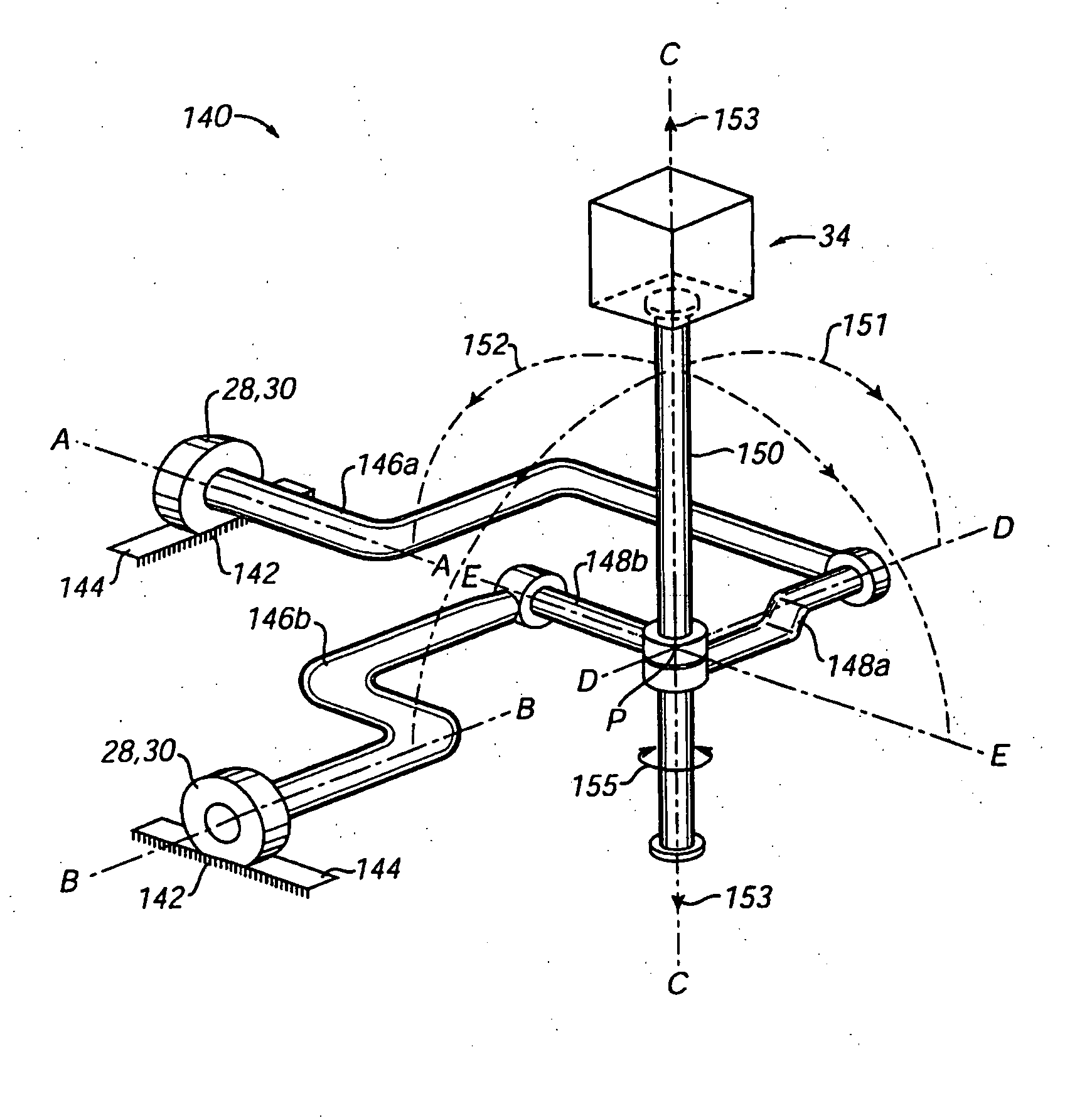
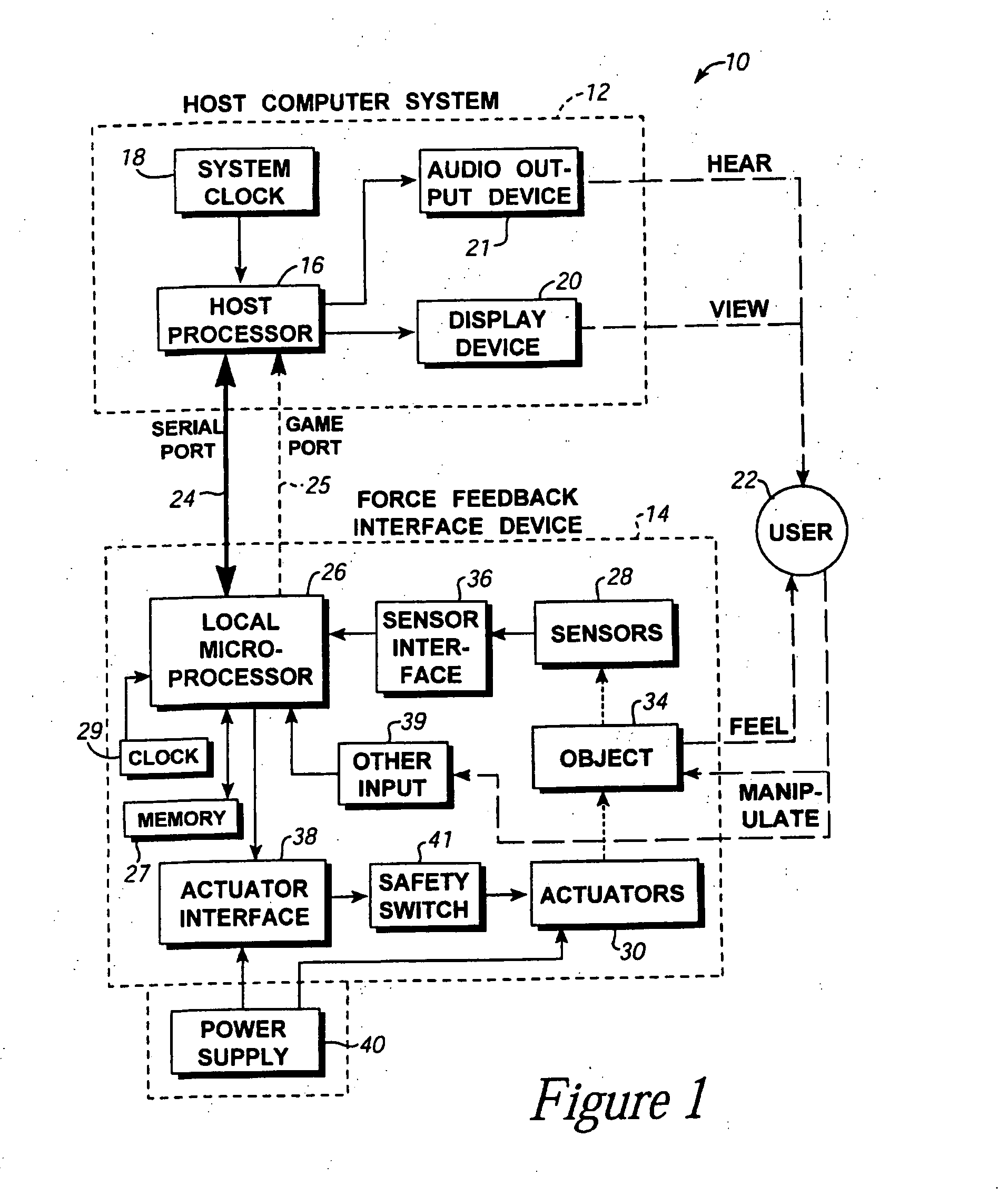
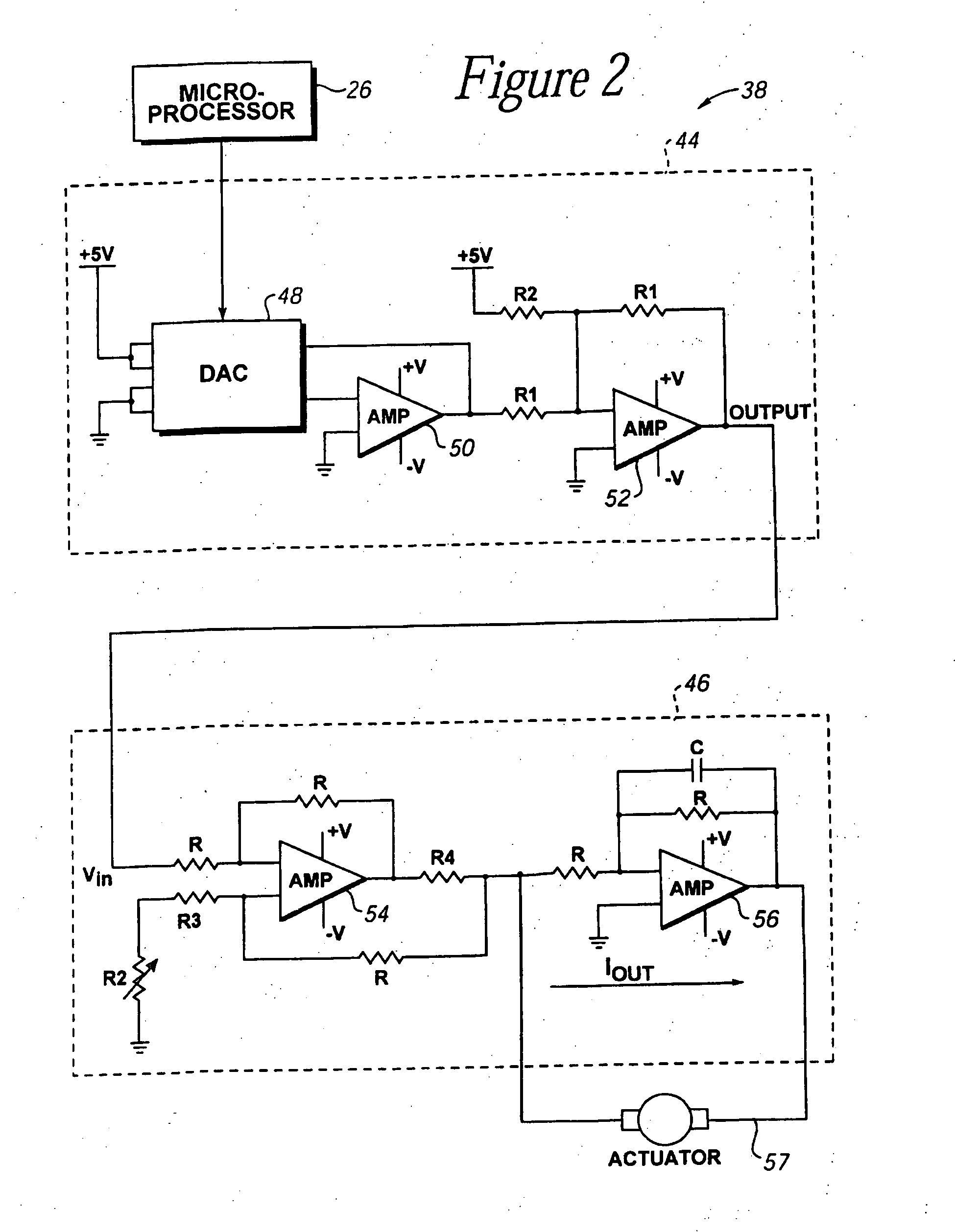
The present invention provides a method for controlling and providing force feedback to a user operating a human / computer interface device in a computer system. The device includes a physical object, such as a joystick or mouse, that the user manipulates to control a cursor in a graphical user interface. The force feedback is provided through an actuator that applies a force to the physical object based on the position of the cursor in the GUI. The force sensation is determined by the location of the cursor in relation to the graphical objects in the GUI. The force sensation can be used to assist or inform the user in selecting the desired function of the graphical object. The force sensation can be adjusted based on the velocity or acceleration of the cursor, and can be associated with different targets in the GUI. The system includes a host computer system and a local microprocessor that work together to provide the force feedback. The technical effect of the invention is to improve the user's experience when interacting with the computer system through the interface device.

Problems solved by technology

The movement of a cursor onto various displayed graphical objects of a GUI may require significant dexterity.
Users may move the cursor too far over an object and have to backtrack their cursor.
In addition, a user may become confused as to which window a cursor is positioned in if the user is viewing other data on the screen at the same time as moving the cursor.
In particular, persons with neuromotor disabilities who suffer from spastic manual control have much greater difficulty interacting with GUI's because they lack the fine motor coordination required to manually position the computer cursor accurately and efficiently.
While manual targeting activities are adequately executed by persons with normal neuromotor functionality, persons with spastic hand motions find such tasks to be physically challenging if not impossible.

Method used


Image

  • Providing force feedback to a user of an interface device based on interactions of a user-controlled cursor in a graphical user interface
  • Providing force feedback to a user of an interface device based on interactions of a user-controlled cursor in a graphical user interface
  • Providing force feedback to a user of an interface device based on interactions of a user-controlled cursor in a graphical user interface

Examples


first embodiment

[0088]FIG. 4 is a flow diagram illustrating a method 70 for controlling a force feedback interface device of the present invention. Method 70 is directed to a “host-controlled” embodiment, in which host computer system 12 provides direct, low-level force commands to microprocessor 26, and the microprocessor directly provides these force commands to actuators 30 to control forces output by the actuators.

[0089] For example, the host controlled mode is suitable for embodiments using a USB communication interface. Data rates are sufficiently high to allow the host to communicate at 500 Hz or greater and provide realistic force feedback to the user object 34. The USB Isochronous Data Transfer mode of USB is suitable to provide the necessary high data rate.

[0090] The process begins at 72. In step 74, host computer system 12 and interface device 14 are powered up, for example, by a user activating power switches. After step 74, the process 70 branches into two parallel (simultaneous) proc...

second embodiment

[0114]FIG. 5 is a flow diagram illustrating a method 100 for controlling force feedback interface device 14 of the present invention. Method 100 is directed to a “reflex” embodiment, in which host computer system 12 provides only high-level supervisory force commands (“host commands”) to microprocessor 26, while the microprocessor independently determines and provides low-level force commands (force values) to actuators 30 as an independent “reflex” to control forces output by the actuators.

[0115] The process of FIG. 5 is suitable for low speed communication interfaces, such as a standard RS-232 serial interface. However, the embodiment of FIG. 5 is also suitable for high speed communication interfaces such as USB, since the local microprocessor relieves computational burden from host processor 16. In addition, this embodiment can provide a straightforward command protocol, an example of which is described with respect to FIGS. 9 and 14, and which allow software developers to easily...


PUM


Abstract

A method and apparatus for providing force feedback to a user operating a human / computer interface device in conjunction with a graphical user interface (GUI) displayed by a host computer system. A physical object, such as a joystick or a mouse, controls a graphical object, such as a cursor, within the GUI. The GUI allows the user to interface with operating system functions implemented by the computer system. A signal is output from the host computer to the interface device to apply a force sensation to the physical object using one or more actuators. This desired force sensation is associated with at least one of the graphical objects and operating system functions of the graphical user interface and is determined by a location of the cursor in the GUI with respect to targets that are associated with the graphical objects. The graphical objects include icons, windows, pull-down menus and menu items, scroll bars (“sliders”), and buttons. The force sensation assists the user to select a desired operating system function or physically informs the user of the graphical objects encountered by the cursor within the GUI. A microprocessor local to the interface apparatus and separate from the host computer can be used to control forces on the physical object.

Description

CROSS-REFERENCE TO RELATED APPLICATIONS [0001] This application is a continuation of U.S. application Ser. No. 09 / 756,617, entitled “Providing Force Feedback to a User of an Interface Device Based on Interactions of a User-Controlled Cursor in a Graphical User Interface,” filed Jan. 3, 2001, which is a continuation of U.S. application Ser. No. 08 / 571,606, entitled “Method for Providing Force Feedback to a User of an Interface Device Based on Interactions of a Controlled Cursor with Graphical Elements in a Graphical User Interface”, filed Dec. 13, 1995, which issued as U.S. Pat. No. 6,219,032 on Apr. 17, 2001, which is a continuation-in-part of U.S. application Ser. No. 08 / 566,282, entitled “Method and Apparatus for Controlling Force Feedback Interface Systems Utilizing a Host Computer”, filed Dec. 1, 1995, which issued as U.S. Pat. No. 5,734,373 on Mar. 31, 1998.BACKGROUND OF THE INVENTION [0002] The present invention relates generally to interface devices for allowing humans to int...

Claims


Application Information

Patent Timeline
Patent Type & Authority Applications(United States)
IPC IPC(8): G09G5/08G05G9/047G06F3/00G06F3/01G06F3/038H04L29/06
CPCA63F13/06A63F2300/1025A63F2300/1037G05G9/047G05G2009/04766G05G2009/04777G06F3/016G06F3/0383G06F3/04812G06F2203/014G06F2203/015H01H2003/008H04L67/38H04L67/131A63F2300/308A63F2300/8017A63F13/57A63F13/285A63F2300/64A63F13/23A63F13/21A63F13/533A63F13/803G06F3/038
Inventor ROSENBERG, LOUIS B.BRAVE, SCOTT B.
Owner IMMERSION CORPORATION
Learn More