Eureka AIR delivers breakthrough ideas for toughest innovation challenges, trusted by R&D personnel around the world.

Diaphragm for speaker device, speaker device and mobile phone

Inactive Publication Date: 2007-06-21
PIONEER CORP +1
View PDF2 Cites 14 Cited by
  • Summary
  • Abstract
  • Description
  • Claims
  • Application Information

AI Technical Summary

Benefits of technology

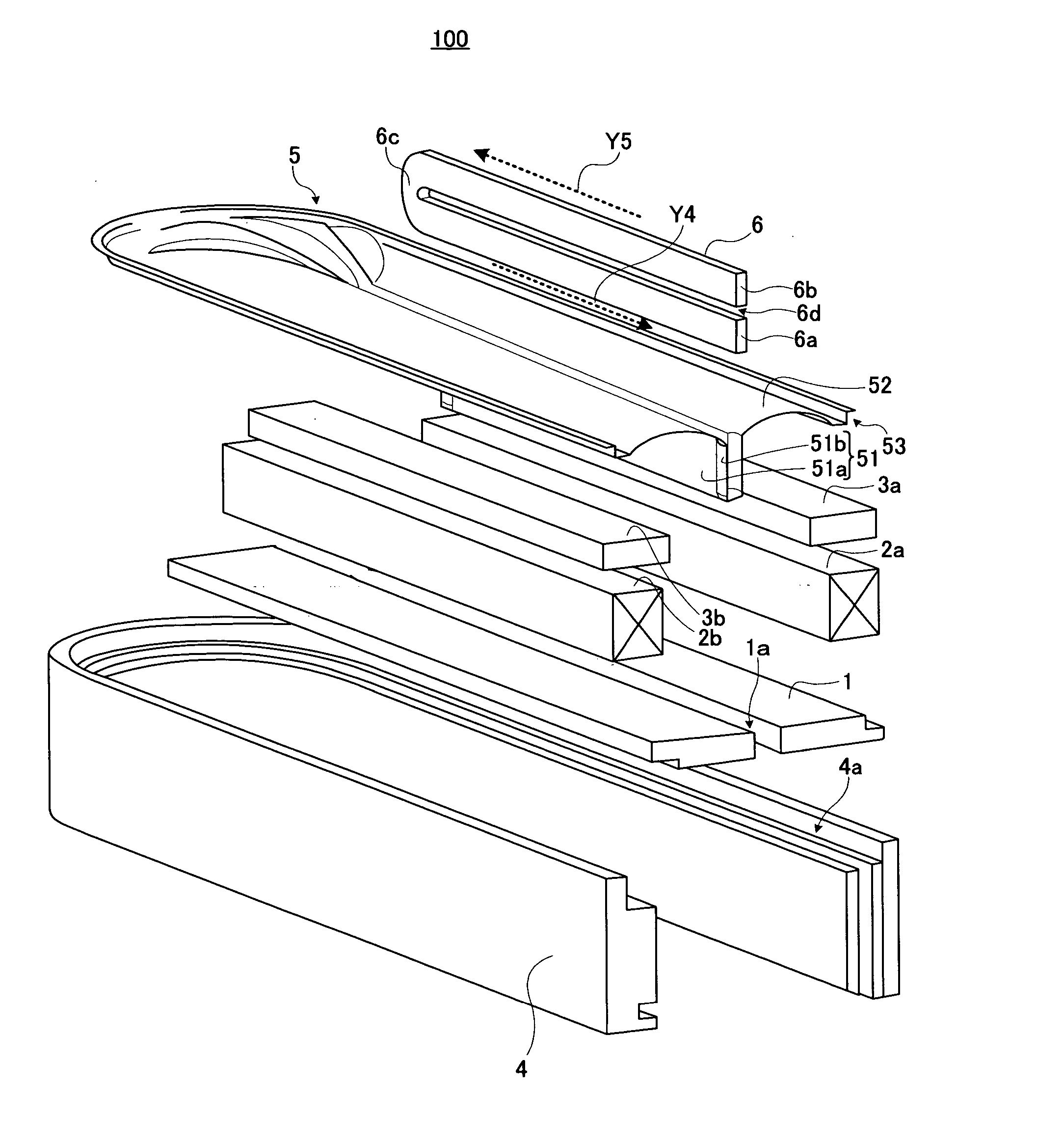
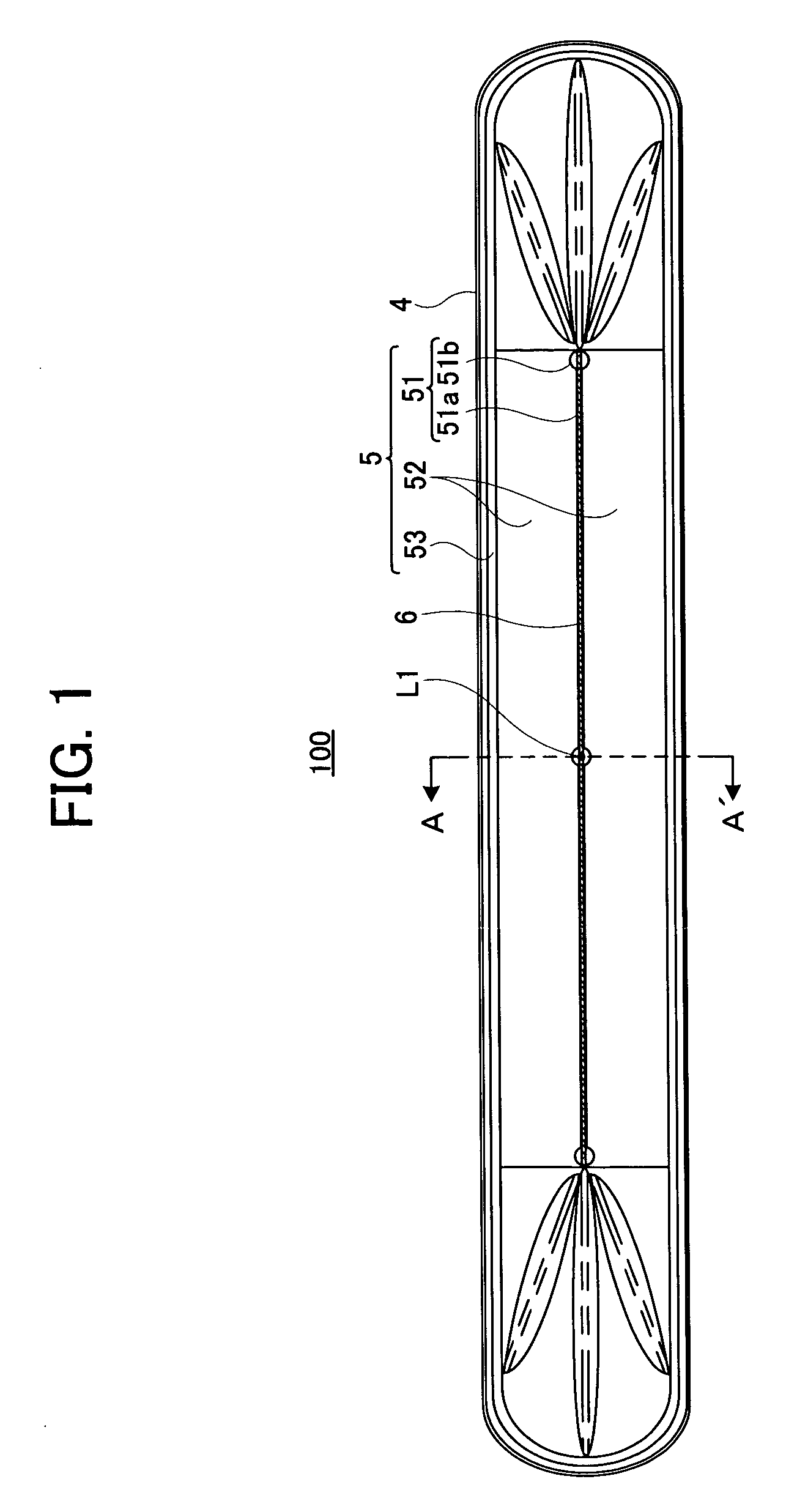
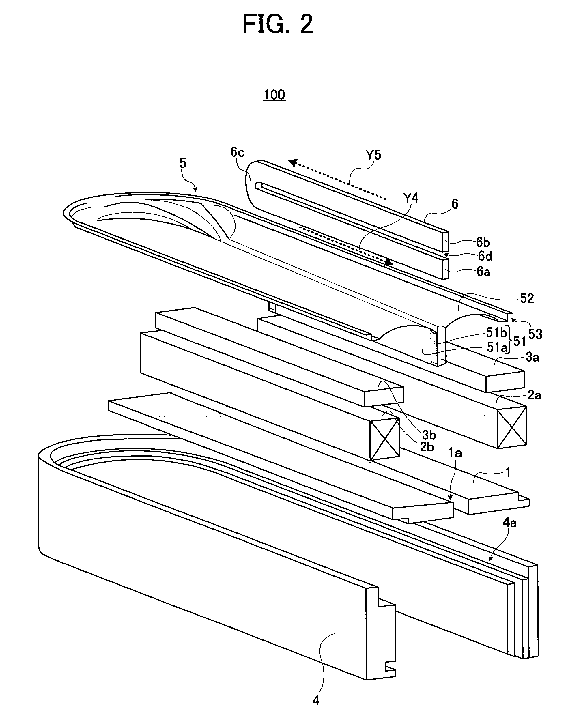
[0010] The present invention has been achieved in order to solve the above problem. It is an object of this invention to provide a diaphragm for a speaker device and a speaker device employing the diaphragm, having an elongated configuration capable of reducing rolling without providing a damper.

Problems solved by technology

Then, it may happen that, in the magnetic gap, the central part of the diaphragm and the magnetic circuit contact or collide and an abnormal sound occurs.

Method used


Image

  • Diaphragm for speaker device, speaker device and mobile phone
  • Diaphragm for speaker device, speaker device and mobile phone
  • Diaphragm for speaker device, speaker device and mobile phone

Examples


application example

[Application Example to Mobile Phone]

[0083] Next, a description will be given of such an example that the speaker device 100 according to the embodiment of the present invention is applied to a receiver part and a call-indicating part of the mobile phone.

[0084]FIG. 10 is a schematic plane view showing a configuration of the mobile phone. A mobile phone 800 shown in the drawing includes plural control bottoms 800a, a display part 800b, an ear piece 800c, a mouth piece 800d, all of which are provided on a front side of a case 800g, a call-indicating part 800e provided on a back side of the case 800g and having a function to make a call-receiving alarm sound, and a transmitting and receiving antenna 800f provided on one side surface of the case 800g. A receiver part 800ca is provided in the case 800g corresponding to the position of the ear piece 800c. In the mobile phone 800 having the above configuration, the speaker device 100 capable of reducing rolling is loaded on the case 800g ...


PUM


Abstract

A diaphragm of a speaker device, formed into an elongated configuration, has a recessed shape and includes a voice coil arrangement part extending in its longitude direction. The voice coil arrangement part has a gap with a constant width in its lateral direction and includes a voice coil supporting part for supporting a voice coil and an expanded part provided at a position along it.

Description

BACKGROUND OF THE INVENTION [0001] 1. Field of the Invention [0002] The present invention relates to a configuration of a diaphragm for a speaker device preferably usable for a mobile phone. [0003] 2. Description of Related Art [0004] Conventionally, there is known a dome-shaped speaker including a dome-shaped diaphragm having a voice coil form having a U-shaped cross-section (see Japanese Patent Application Laid-open under No. 5-30592 (p. 5, FIG. 6), which is referred to as “Reference-1” hereinafter). [0005] In the dome-shaped speaker disclosed in Reference-1, since the voice coil is arranged in the voice coil form having the U-shaped cross-section, the driving force of the voice coil directly operates on the voice coil form at the time of sound reproduction. Therefore, the strength capable of enduring the driving force of the voice coil is necessary for the voice coil form. In this point, since the voice coil form is formed into a circular or track shape and an annular shape, it c...

Claims


Application Information

Patent Timeline
IPC IPC(8): H04R9/06H04R1/00H04R11/02
CPCH04R7/127H04R9/025H04R9/045H04R2499/11
Inventor KONUMA, SHINSUKEFURUTO, AKIHIKOMITOBE, KUNIO
Owner PIONEER CORP
Why Eureka
Eureka Blog
Learn More