Suspension structure and connecting mode of bridgeless automobile

A suspension and frame technology, which is applied in the field of suspension structure and connection method of bridgeless vehicles, can solve the problems of left and right shaking of the vehicle body, tail flicking, lack of steering centrifugal force and weight support, etc.

Pending Publication Date: 2019-10-18
杨晓东
View PDF0 Cites 6 Cited by
  • Summary
  • Abstract
  • Description
  • Claims
  • Application Information

AI Technical Summary

Problems solved by technology

[0010] In view of the above-mentioned lack of scientific structure of the driving system, the structure of the driving system lacks the control function of the steering centrifugal force and the function of self-adjusting the balance of the center of gravity support on both sides, so that the weight support of the wheels on both sides of the car body is unclear. At the same time, the two sides The side suspension system and the frame and wheels form a rectangular parallelepiped rigid connection through the front and rear axles or other components, so that the driving system cannot immediately realize the self-adjustment of the support balance of the center of gravity on both sides of the car body and tire wear when encountering changes in the road shape and the center of gravity of the car body. Faster problems, the biggest defect is that the wheels, suspension system, and the frame, axle or load-bearing body are horizontally connected to form a whole with lateral force, and the left and right wheel sides become the lever fulcrum for the lateral force of the car body. When the center of gravity of the car body deviates laterally from one side, the wheels and all elastic elements on one side are suppressed by gravity to lower their support, while the wheels and elastic elements on the other side are under the action of tire pressure and elastic force of the suspension elastic elements. If the support is rapidly increased, the lateral center of gravity of the upper part of the car body must be biased towards the weaker side of the support. With the further reduction of the road surface or the further deepening of the turning, as well as the simultaneous action of the steering centrifugal force and inertial force, the inclination of the upper part of the car body will increase, resulting in The wheel on one side with weak support is used as a support point to pry up the wheel on the other side through the left and right steel lateral force transmission, so that the grounding and direction control performance of the wheel on this side will deteriorate. The problem that the vehicle rolls over due to the failure of the direction

Method used


Image

  • Suspension structure and connecting mode of bridgeless automobile
  • Suspension structure and connecting mode of bridgeless automobile
  • Suspension structure and connecting mode of bridgeless automobile

Examples


Embodiment 1

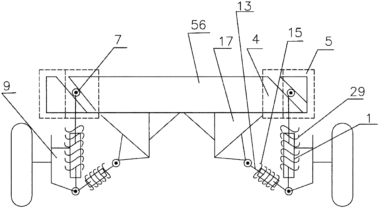
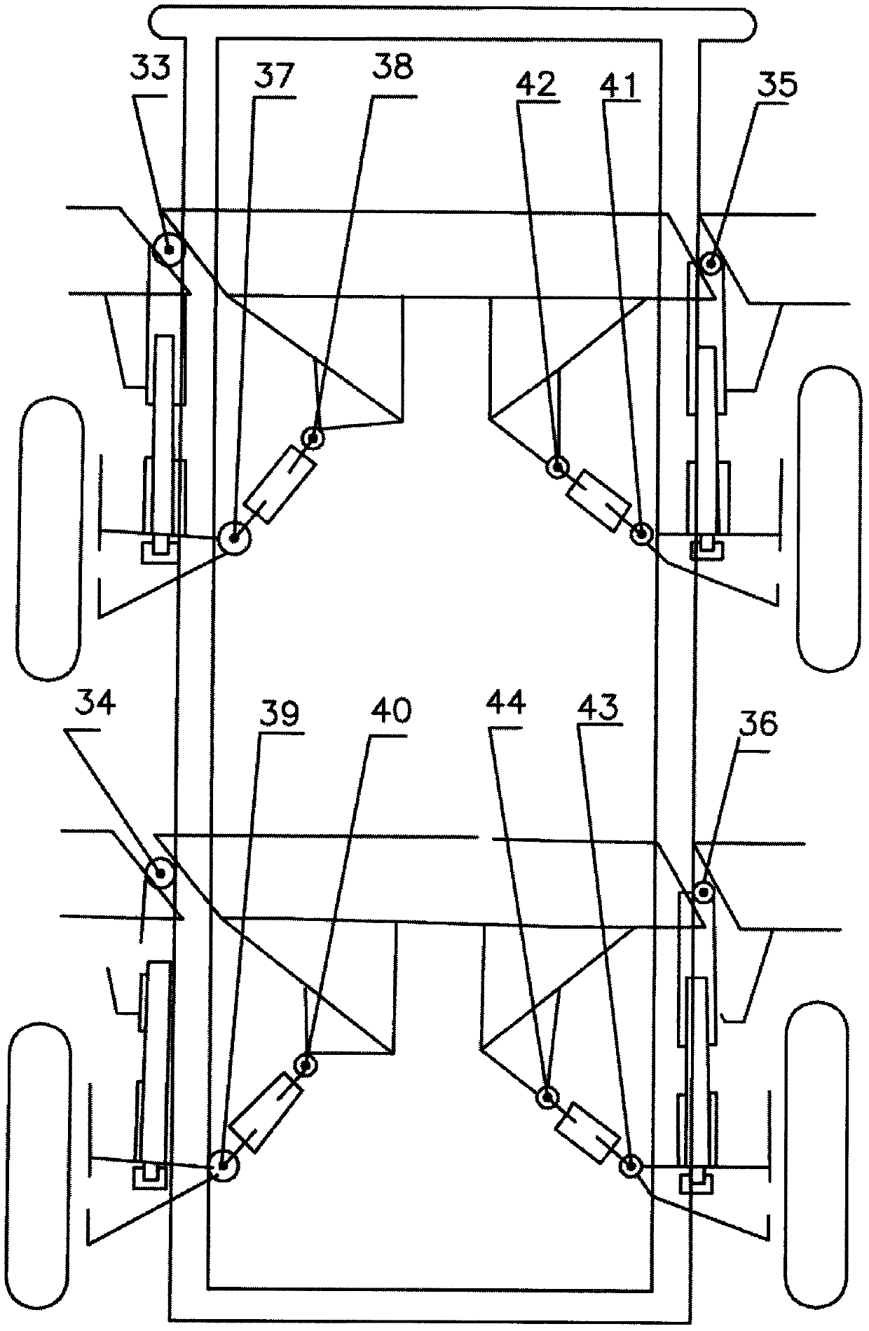
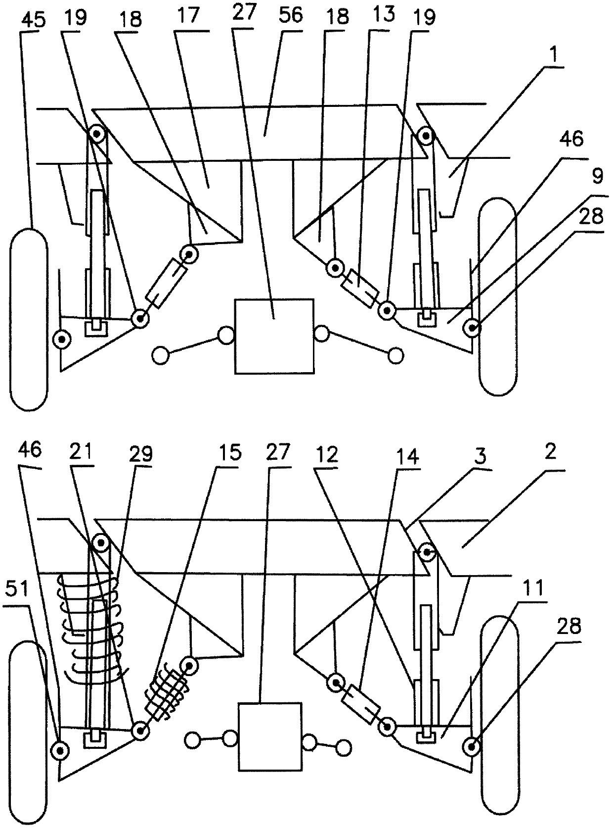
[0045] Such as Figure 1 to Figure 7 As shown, a suspension structure and connection method of a bridgeless automobile, wherein the main components and connection method in the suspension structure of a bridgeless automobile include a conical hydraulic shock absorber 1, a 45-degree slope suspension upper end interface 2, 45-degree slope frame interface 3, frame hinge shaft connecting plate 4, suspension hinge shaft connecting plate 5, suspension positioning bushing 6, suspension hinge shaft 7, fastening screw 8, front wheel support assembly 9, front Suspension fixing and steering rotation auxiliary connection device 10, rear wheel support assembly 11, rear suspension connection and fixing device 12, front wheel lateral hydraulic support stabilizer bar 13, rear wheel lateral hydraulic support stabilizer bar 14, wheel lateral support return spring 15. Frame or load-bearing body 16. Subframe 17. Horn support seat assembly 18. Front wheel support assembly lateral hydraulic support...

Embodiment 2

[0052] This embodiment is further limited on the basis of Embodiment 1: as a technical solution with a simple structure and easy processing, manufacturing and assembly, the first to twelfth hinges are hinged and rotated, and the hinge shaft 7 The length direction of , 24 is consistent with the length direction of the vehicle, that is, the length direction of the hinge shaft is parallel to the length direction of the vehicle frame or load-bearing body 16, and the axis direction of the cross shaft 22 and the connection end of the front wheel lateral hydraulic support stabilizer bar is hinged with the suspension The shaft 7 is in the same length direction as the hinge shaft 24 of the front wheel lateral hydraulic support stabilizer bar. Since the small journal section of the suspension hinge shaft is in direct contact with the surface of the needle roller bearing, the machining accuracy and heat treatment hardness of the surface should be the same as that of the inner bearing. Cir...


PUM


Abstract

The invention provides a suspension structure and connecting mode of a bridgeless automobile and relates to the technical field of automobile running system structures. The invention discloses the suspension structure and connecting mode of the bridgeless automobile. The suspension structure and connecting mode of the bridgeless automobile comprises the steps of hinging and connecting the upper ends of left and right side suspensions of a frame to form a rotation point; hinging and connecting the lower ends of the left and right side suspensions with left and right side wheel supporting assemblies and one end of a transverse hydraulic supporting stabilizing bar to form rotation points; hinging and connecting the other end of the transverse hydraulic supporting stabilizing bar with a steering knuckle supporting seat assembly on a sub frame to form a rotation point; when the upper part of a vehicle body is inclined to one side under the influence of steering centrifugal force, the bottomof the sub frame can swing to one side reverse to the direction of the centrifugal force; during swinging, the tail end of a steering knuckle extrudes the transverse hydraulic supporting stabilizingbar to retract so that the transverse supporting distance of this side is shortened and the supporting position of this side is lowered; a hinging part on an associated side is enabled to rotate so that the gravity force of the vehicle body is naturally lowered to automatically offset the steering centrifugal force; and therefore, the supporting balance of the gravity centers, on the left and right sides, of the vehicle body is automatically adjusted.

Description

technical field [0001] The invention relates to the technical field of a suspension structure of an automobile driving system, in particular to a suspension structure and a connection method of a bridgeless automobile. Background technique [0002] The stability and safety of automobile driving is the key technology in automobile design and manufacturing, which involves the safety of people's lives and property. my country is a populous country in the world. In recent years, with the continuous improvement of my country's economy and living standards, the number of automobiles has increased However, in the face of the situation that my country's automobile industry is large but not strong and future automobiles need to be energy-saving, environmentally friendly, safe and reliable, and the development trend of lightweight, intelligent and electrified automobiles, vehicle safety is one of the key technologies for competition in the automobile market 1. At present, due to the rap...

Claims


Application Information

Patent Timeline
Patent Type & Authority Applications(China)
IPC IPC(8): B60G13/06B60G17/00B60G21/073
CPCB60G13/06B60G17/00B60G21/073B60G2202/24B60G2500/00
Inventor 杨晓东
Owner 杨晓东
Why Eureka
Try Eureka