Modularly constructed rotorblade and method for construction

a modular construction and rotorblade technology, applied in the field of rotorblade construction, can solve the problems of increasing the possibility of surface abnormalities or defects at these aerodynamically critical points, affecting the field performance of the blade, and affecting the efficiency of the blad

Active Publication Date: 2007-06-21
GENERAL ELECTRIC CO
View PDF22 Cites 72 Cited by
  • Summary
  • Abstract
  • Description
  • Claims
  • Application Information

AI Technical Summary

Problems solved by technology

While blades as described above are commercially accepted, there are field performance and efficiency issues that are related to the current construction and bonding of these large blades.
One such issue pertains to the creation of a bonding line continuously along the leading and trailing edges of the blade.
Bonding along the leading and trailing edges using a thick adhesive increases the possibility for surface abnormality or defect at these aerodynamically critical points.
These surface abnormalities impact field performance of the blade, including erosion at the leading edge bonding line.
Another issue pertains to the relatively large length of the pre-bonded blade halves.
Molding blades in such large blade sections (halves) leads to inefficient tooling costs in that each section involves a protracted molding process that requires extensive preparation, and thus slow turn-around.
In addition, these blades or blade halves must be transported to various sites for further assembly and / or use, and transportation of such lengthy structures can lead to high transportation expenditures, as they are difficult to haul via conventional tractor-trailers.

Method used


Image

  • Modularly constructed rotorblade and method for construction
  • Modularly constructed rotorblade and method for construction
  • Modularly constructed rotorblade and method for construction

Examples


Embodiment Construction

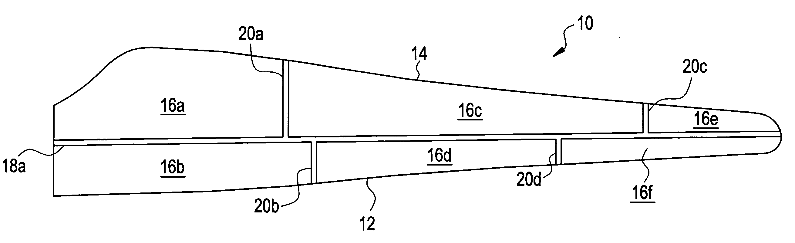
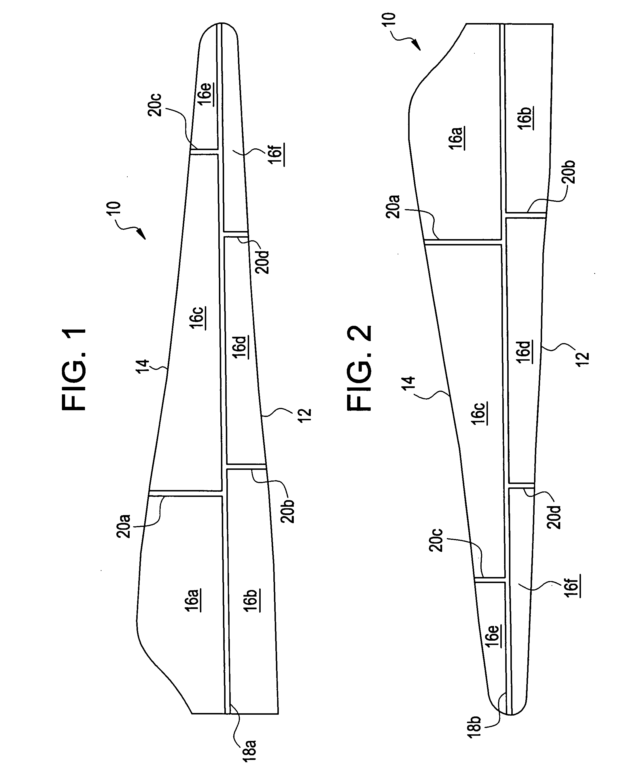
[0019] Referring to FIG. 1 and FIG. 2, an exemplary embodiment of a modularly constructed rotorblade 10 is illustrated and includes a leading edge 12, a trailing edge 14, and a plurality of rotorblade sections in bonded association. At least one bonding line is representative of a seam or region at which the plurality of rotorblade sections are bonded (i.e. where the bonded associations take place), wherein any adhesive bonding substance necessary to the desired end purpose may be used. Each of the at least one bonding line is disposed away from continuous contact with the leading edge 12 and / or the trailing edge 14 of the rotorblade 10. This disposal away from continuous contact with the leading edge 12 and / or the trailing edge 14 does not exclude bonding lines that intersect the leading edge 12 and / or trailing edge 14, but does exclude lines that run in continuous contact (or continuously along) the leading edge 12 and / or trailing edge 14. By disposing the at least one bonding lin...


PUM


Abstract

Disclosed is a modularly constructed rotorblade including a leading and a trailing edge, including a plurality of rotorblade sections in bonded association, and at least one bonding line disposed away from continuous contact with the leading edge and the trailing edge.

Description

FIELD OF THE INVENTION [0001] This disclosure relates generally to a rotorblade, and more particularly to rotorblade construction. BACKGROUND OF THE INVENTION [0002] Rotorblades, such as those used in wind turbines, are typically constructed by molding two sections or halves of the blade, and then bonding the halves using an adhesive. The two halves are bonded continuously along the leading and trailing edges of the blade using a relatively thick line of adhesive. These blades, and their respective halves can be very large measuring over 100 feet in length. [0003] While blades as described above are commercially accepted, there are field performance and efficiency issues that are related to the current construction and bonding of these large blades. One such issue pertains to the creation of a bonding line continuously along the leading and trailing edges of the blade. Bonding along the leading and trailing edges using a thick adhesive increases the possibility for surface abnormali...

Claims


Application Information

Patent Timeline
Patent Type & Authority Applications(United States)
IPC IPC(8): B64C27/46
CPCF03D1/0675Y02E10/721Y02E10/72
Inventor BAKHUIS, JAN WILLEMBILLEN, ANDREW JOHNVAN BREUGEL, SJEFLIVINGSTON, JAMIE THOMAS
Owner GENERAL ELECTRIC CO
Why Eureka
Try Eureka