

Rechargeable battery and battery module
a rechargeable battery and battery module technology, applied in cell components, electrochemical generators, jackets/cases materials, etc., can solve the problems of inability to apply pressure uniformly to the entire pouch, difficulty in applying a separate structure for improving a heat radiating property, etc., and achieve constant pressure and prolonging the battery life
- Summary
- Abstract
- Description
- Claims
- Application Information
AI Technical Summary
Benefits of technology
Problems solved by technology
Method used
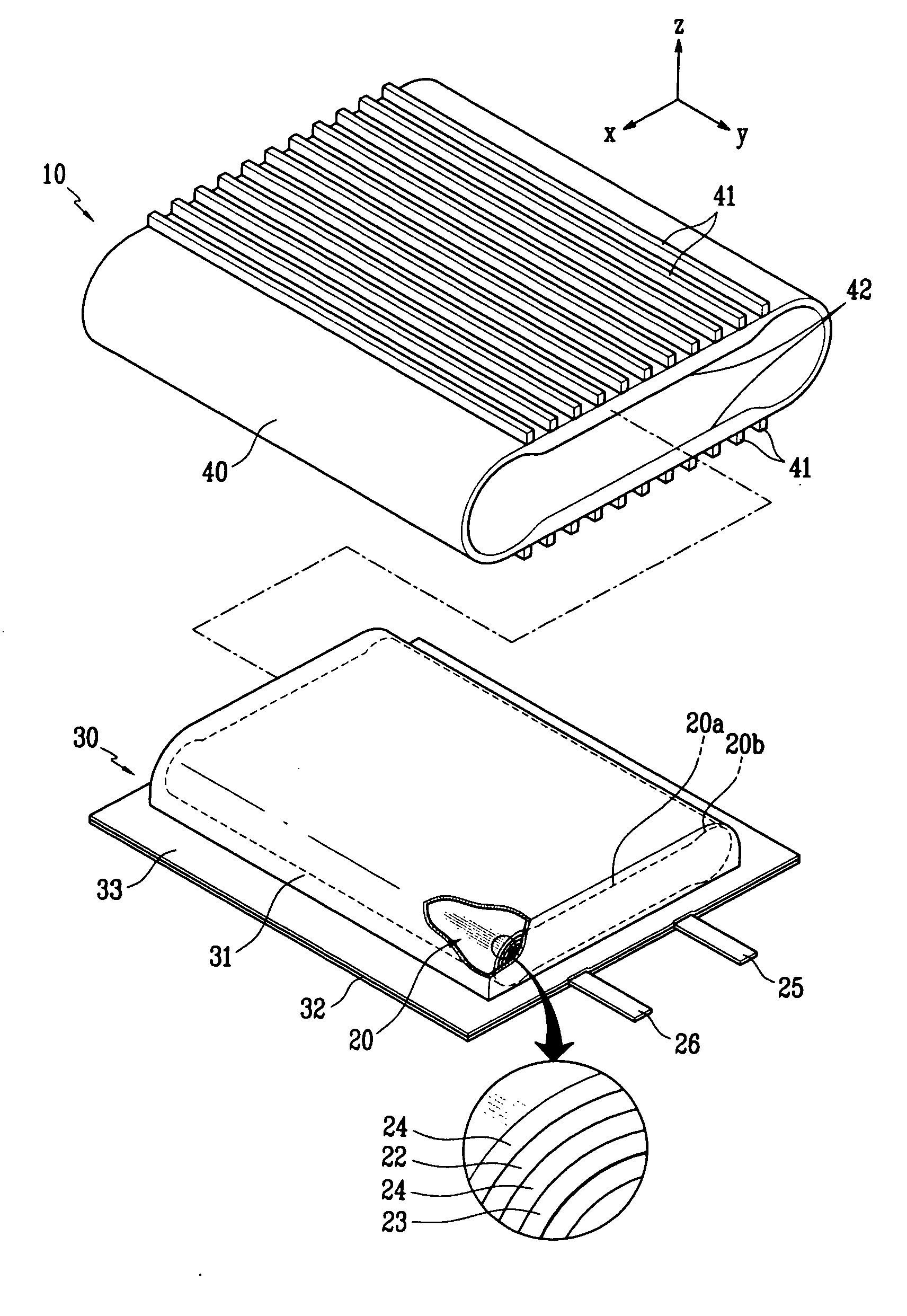
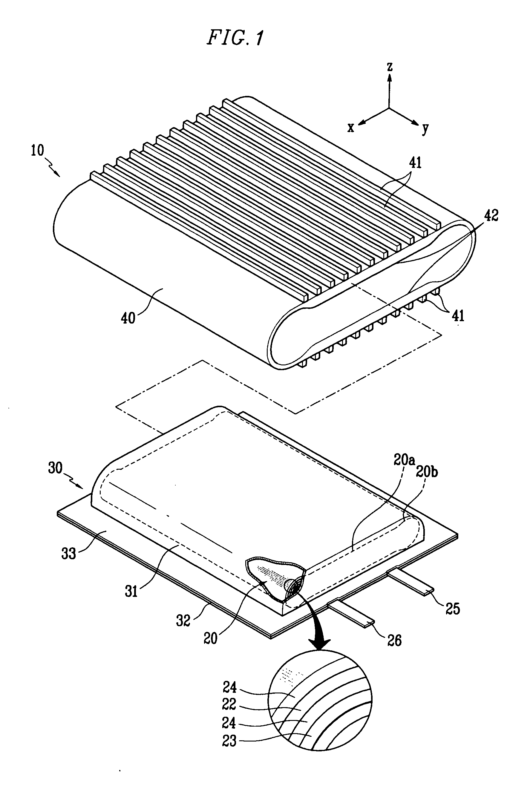
Image

Examples
second embodiment
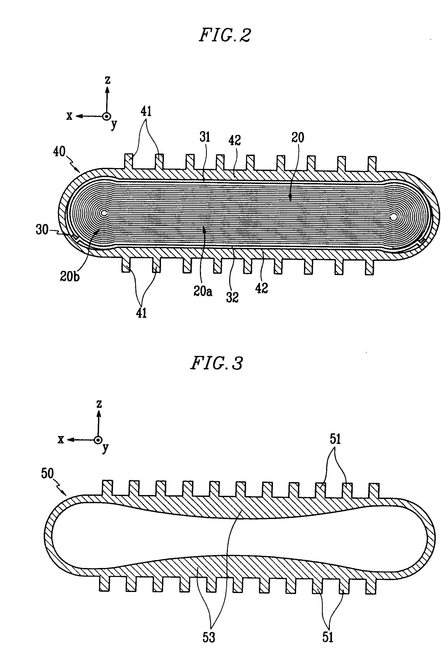
[0062]FIG. 3 is a cross-sectional view showing the heat dissipating body according to the present invention.
[0063] As seen in FIG. 3, a heat dissipating body 50 includes a convex part 53 for applying pressure to planar part 20a of the electrode assembly 20 (shown in FIG. 1), the convex part 53 protruding in an arc shape forming a gentle curve toward the inside of the heat dissipating body 50. Thus, the convex part 53 grows thicker from the both ends thereof towards the middle thereof.
first embodiment
[0064] In addition, the heat dissipating body 50 includes multiple heat radiating ribs 51, the heat radiating ribs 51 have the same structure as that of the heat radiating ribs according to the above-described
[0065] The heat dissipating body 50 according to the present embodiment is formed in a continuously curved shape, thereby preventing a non-constant pressure from being applied to the electrode assembly 20 in a discontinuous portion thereof, such as a corner.
third embodiment
[0066]FIG. 4 is a cross-sectional view showing a heat dissipating body according to the
[0067] As seen in FIG. 4, the heat dissipating body 60 according to the present embodiment includes a convex part 64 which extends from the outside to the inside at both sides opposed each other to protrude to the inside. Thus, at the portion in which the convex part 64 is formed, the space between the inside surfaces is shortened.
[0068] In other words, the heat dissipating body 60 has a constant thickness and in the middle thereof, the convex part 64 is extended inward. The convex part 64 has a cross-section of a straight line shape for stably supporting the planar part 20a of the electrode assembly 20 (shown in FIG. 1).
[0069] In addition, on both sides of the convex part 64, a surface having a section of a circular arc connects the convex part 64 opposed each other, thus the heat dissipating body 60 has a sectional structure of a dumbbell shape. In addition, on the outside surface of the heat ...
PUM
| Property | Measurement | Unit |
|---|---|---|
| spatial area | aaaaa | aaaaa |
| pressure | aaaaa | aaaaa |
| thickness | aaaaa | aaaaa |
Abstract
Description
Claims
Application Information