
Radio communication apparatus and method

a radio communication and radio communication technology, applied in the field of multi-input multi-output radio communication apparatus and method, can solve the problem of large amount of computation in the field of technology, and achieve the effect of maximizing channel capacity and channel capacity

Active Publication Date: 2007-06-21
SAMSUNG ELECTRONICS CO LTD
View PDF33 Cites 20 Cited by
  • Summary
  • Abstract
  • Description
  • Claims
  • Application Information

AI Technical Summary

Benefits of technology

The present invention provides a radio communication device with multiple reception antennas that have different patterns. This allows for better identification of channels within the system. A channel matrix estimation unit determines which combinations of antenna patterns provide maximum performance based on the identified channels. An antenna pattern control unit then changes the settings of these antennas to optimize their performance. These technical improvements result in improved signal quality and more reliable data transfer at higher speeds over longer distances.

Problems solved by technology

The technical problem addressed in this patent relates to improving communication capacity in WLAN networks using MIMO technology while controlling the direction of individual antennas to increase efficiency. Existing technologies require significant computing resources and result in limited flexibility of antenna patterns due to their continuity and variability.

Method used


Image

  • Radio communication apparatus and method
  • Radio communication apparatus and method
  • Radio communication apparatus and method

Examples


Embodiment Construction

[0022] The present invention will now be described more fully with reference to the accompanying drawings, in which preferred embodiments of the invention are shown.

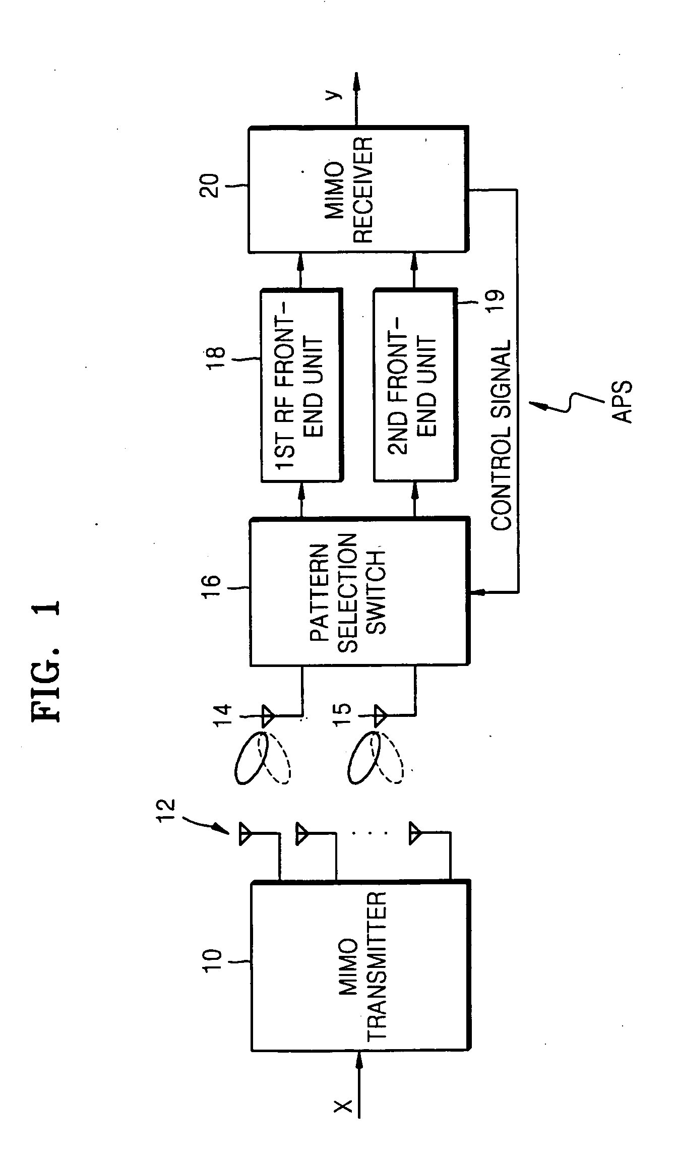
[0023]FIG. 1 is a block diagram illustrating a structure of a radio communication apparatus according to the present invention.

[0024] Referring to FIG. 1, a transmission vector signal (x) is divided in a MIMO transmitter 10 and transmitted to each transmission unit (not shown). The output of each transmission unit is radiated from a plurality of transmission antennas 12.

[0025] The signal radiated from the plurality of transmission antennas 12 is propagated through a transmission path, i.e., a space that can be regarded as parallel multi paths, and arrives at a first reception antenna 14 and a second reception antenna 15. Though the number of reception antennas is being illustrated as 2 for convenience of explanation, the number of reception antennas may be more than 2 and is still within the scope of the present inven...


PUM


Abstract

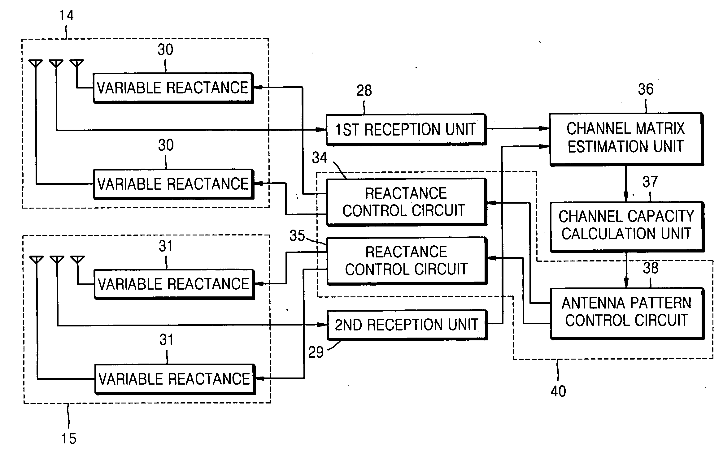
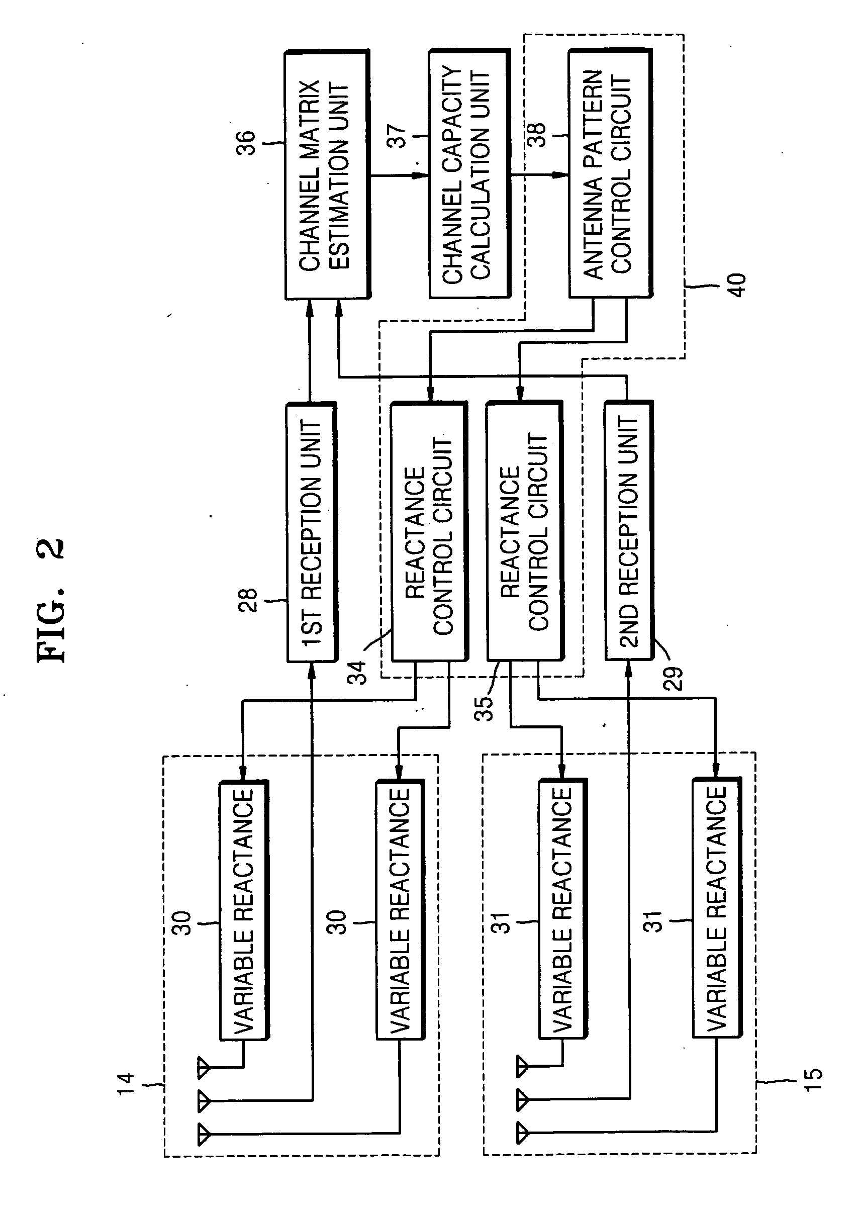
A multi-input multi-output (MIMO) radio communication apparatus and method are provided. The MIMO apparatus includes a plurality of reception antennas each having a plurality of antenna patterns; a channel matrix estimation unit for estimating a channel matrix between a plurality of transmission antennas and the plurality of reception antennas; a channel capacity calculation unit for calculating a channel capacity corresponding to a combination of antenna patterns of the plurality of reception antennas by using the estimated channel matrix; and an antenna pattern control unit for changing the antenna patterns of the plurality of reception antennas to maximize the channel capacity. According to the MIMO radio communication apparatus and method, direction can be controlled adaptively to a propagation environment.

Description


Claims


Application Information

Patent Timeline
Owner SAMSUNG ELECTRONICS CO LTD
Learn More