
A Beam Tracking Coverage and Enhancement Method Based on Smart Reflective Surface

A reflective surface, intelligent technology, applied in the field of communication, can solve the problem that the reflected beam cannot be accurately aligned with the user, and achieve the effect of ensuring continuity and maximizing channel capacity

Active Publication Date: 2021-08-03
BEIJING JIAOTONG UNIV
View PDF0 Cites 0 Cited by
  • Summary
  • Abstract
  • Description
  • Claims
  • Application Information

AI Technical Summary

Problems solved by technology

Most of the existing research has analyzed and optimized the performance of the IRS-assisted communication system, but there is no research on the beam tracking of the user by the IRS-assisted gNB (the 5G base station is named gNB, generation NodeB in 3GPP) after the direct path is interrupted.
In addition, due to factors such as IRS control signal delay and user movement, its reflected beam cannot be accurately aligned with the user.

Method used


Image

  • A Beam Tracking Coverage and Enhancement Method Based on Smart Reflective Surface
  • A Beam Tracking Coverage and Enhancement Method Based on Smart Reflective Surface
  • A Beam Tracking Coverage and Enhancement Method Based on Smart Reflective Surface

Examples


Embodiment 1

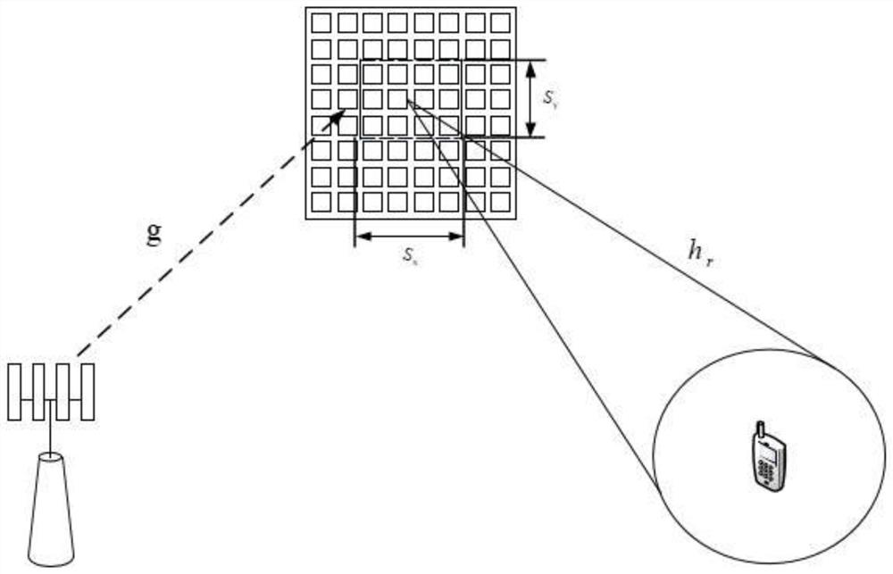
[0053] When the communication link between the gNB and the UE is interrupted due to reasons such as occlusion, the gNB establishes a communication link with the UE through the IRS. Due to the characteristics that millimeter waves are easily blocked and absorbed, the area covered by the IRS unit is only determined by the direct path, and the scattered path is negligible compared with the direct path. The combined channel through which the signal propagated by the IRS unit is the concatenation of the gNB-IRS channel, the IRS unit reflection and the IRS-UE channel, namely Among them, h r is the IRS-UE channel, Indicates the phase shift of the IRS unit, and g is the gNB-IRS channel. definition is the concatenated channel of gNB-IRS and IRS-UE, where, Therefore, after the signal is reflected by the IRS unit, the composite gNB-IRS-UE channel response is shown in formula (1),

[0054]

[0055] in, is the phase shift of the IRS unit, is the corresponding composite chan...

Embodiment 2

[0099] This embodiment provides a method for beam tracking coverage and enhancement based on an intelligent reflective surface, which may specifically include the following steps:

[0100] Scene parameter setting: gNB is a multi-antenna base station, which can control the power of beams transmitted to different units of the IRS panel. The number of units along the x direction of the IRS panel is 32, and the number of units along the y direction is 32. The signal processing delay is 1s.

[0101] Figure 5 It is the effect diagram of the coverage and enhancement of the IRS beam in the case of the user's historical position (10,10) and the movement speed of 3m / s. refer to Figure 5 , the abscissa indicates the x-coordinate of the user's position, the ordinate indicates the y-coordinate of the user's position, and the right side is the channel gain value represented by the color depth, that is, the value of Effective channel gain, the unit is dB, and the color at each point in th...


PUM


Abstract

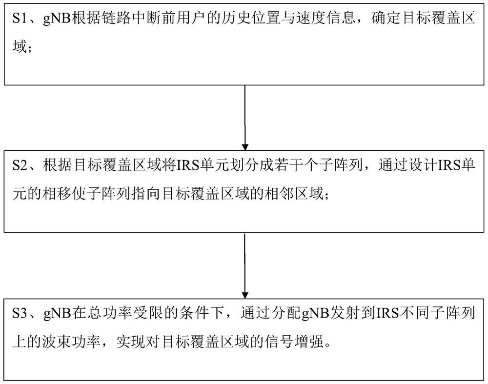
An embodiment of the present invention provides a beam tracking coverage and enhancement method based on an intelligent reflective surface, including the following steps: S1, the gNB determines a target coverage area according to the historical position and speed information of the user before the link is interrupted; S2, according to the target coverage The area divides the IRS unit into several sub-arrays, and the phase shift of the IRS unit is designed to make the sub-array point to the adjacent area of ​​the target coverage area; S3 and gNB transmit to different sub-arrays of IRS by allocating the gNB under the condition of limited total power The beam power on the target area can be enhanced to achieve signal enhancement. Embodiments of the present invention provide a beam tracking coverage and enhancement method based on an intelligent reflective surface, so as to effectively reduce the impact of link interruption caused by occlusion of millimeter wave signals, thereby ensuring the continuity of communication.

Description

technical field [0001] The invention relates to the field of communication technology, in particular to a beam tracking coverage and enhancement method based on an intelligent reflective surface. Background technique [0002] In the past decade, the explosive growth of mobile data and the increasing demand for higher data rates have driven the development of wireless communication technologies, such as massive multiple input multiple output (Multiple Input Multiple Output, MIMO) and millimeter Wave (Millimeter Wave, mmWave) and other communication technologies. [0003] Although MIMO technology has greatly improved the spectrum and energy efficiency of wireless communication systems, the high processing complexity and high hardware cost are still major obstacles in practical implementation, especially in high frequency bands such as mmWave. One challenge of mmWave communication is that the path loss of the signal is much greater on the mmWave frequency band compared to the ...

Claims


Application Information

Patent Timeline
Patent Type & Authority Patents(China)
IPC IPC(8): H04W16/28H04W72/04
CPCH04W16/28H04W72/046H04W72/0473
Inventor 章嘉懿郭雅婧艾渤
Owner BEIJING JIAOTONG UNIV
Learn More