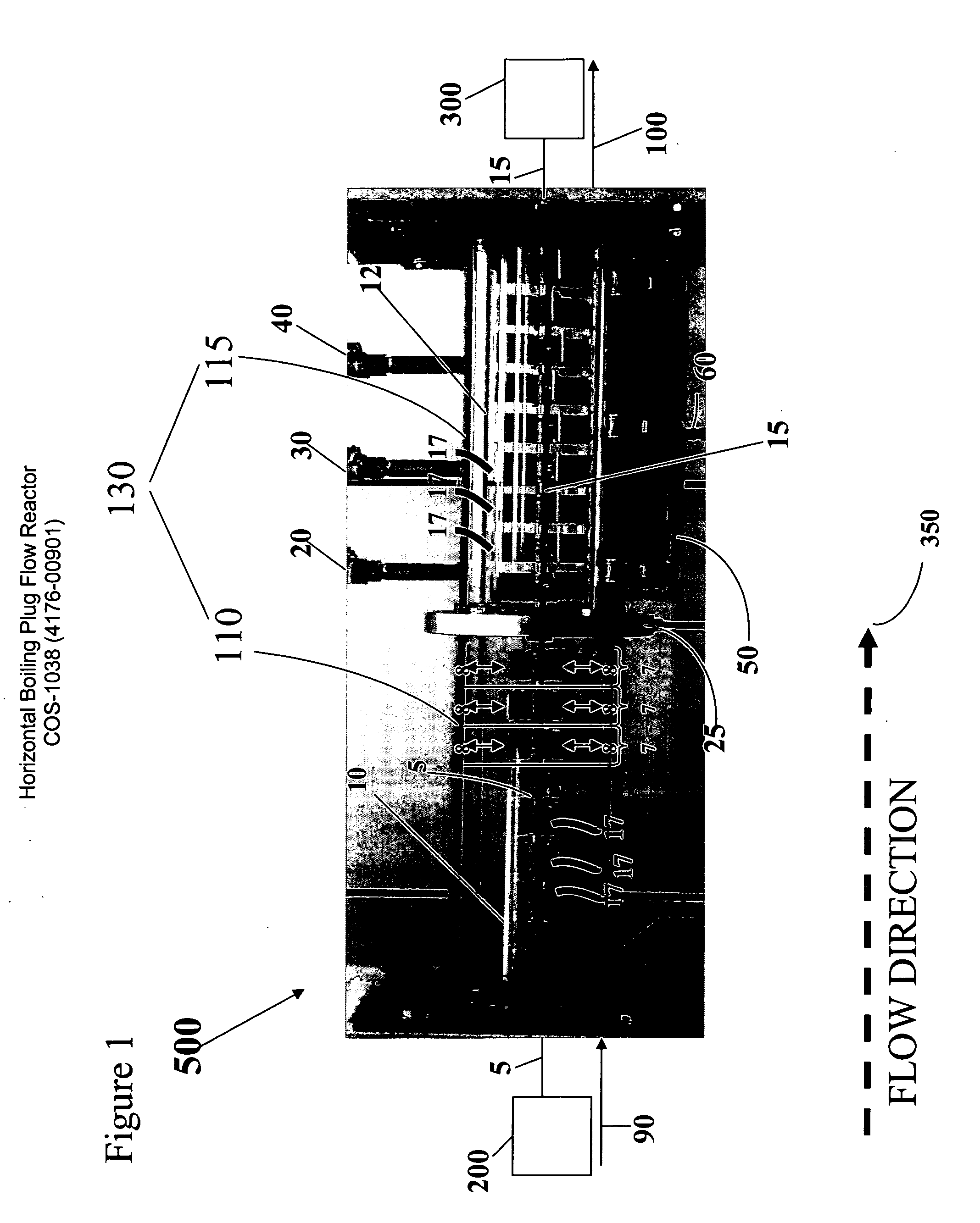
Horizontal boiling plug flow reactor
a flow reactor and horizontal technology, applied in the direction of rotary stirring mixers, transportation and packaging, lighting and heating apparatus, etc., can solve the problem that the pfrs does not allow for easy temperature control
- Summary
- Abstract
- Description
- Claims
- Application Information
AI Technical Summary
Benefits of technology
Problems solved by technology
Method used
Image

Examples
example 1
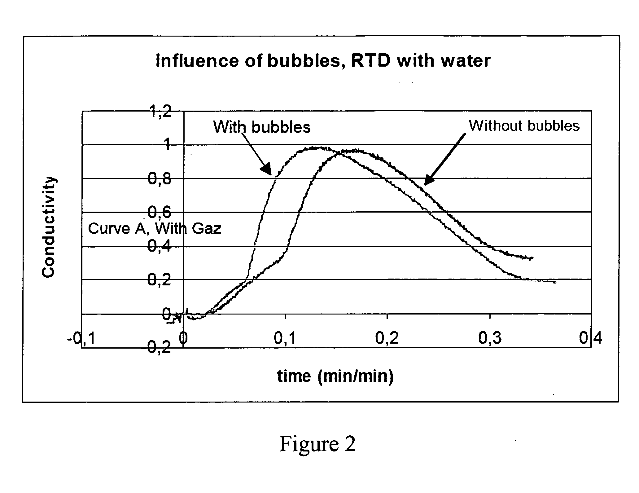
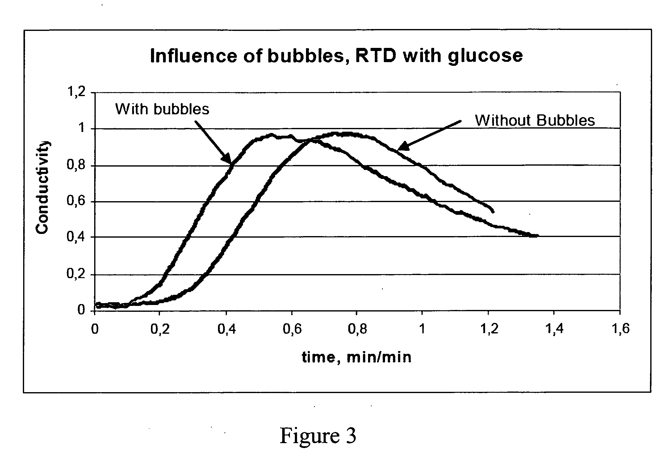
[0049] The influence of the addition of bubbles through the sparging device on the PFR behavior of the HBPFR was determined. Bubbles were found to decrease the mean residence time (RT) for the two viscosities compared. A difference of 2 minutes is observed in the case of water and a difference of 9 minutes in the case of glucose at 2 Pa·s, FIGS. 2 and 3. Concerning the axial dispersion, a significant increase can be noticed for water experiments with bubbles. For experiments at 2 Pa·s, the axial dispersion is similar for the two curves.
[0050] The results of these experiments indicate that in the heterogeneous flow (bubble size distribution), the dispersion coefficient increases in a significant way with the superficial gas velocity. Thus bubbles favor the dispersion mechanism. This result was verified with experiments performed with water. However, for viscosities around 2 Pa·s, bubbles do not induce more axial dispersion to a significant degree. Moreover, bubbles boost the fluid p...
example 2
[0052] The influence of the mechanical flow facilitator on the PFR behavior of the HBPFR was determined. Two types of impeller were tested for the aerated part: the helical ribbon and the swept blade impellers. The non aerated part was equipped with swept blade impellers. FIG. 4 compares the RTD obtained with the two types of impeller: The results indicate that the fluid progression in the reactor is faster with the helical ribbon as shown by a difference of 12 minutes on the mean RT is observed, see FIG. 4. Concerning the axial dispersion, the two curves do not show significant differences. In order to reach the targeted RT, swept blade impellers for the aerated part were also advised.
example 3
[0053] The influence of the rotating speed of the impellers on the PFR behavior of the reactor was determined. The rotating speed in the non-aerated part did not influence the axial dispersion to a significant degree. The mean RT (around 31 minutes) also remained about the same.
[0054] However, the rotating speed of the impellers did affect the RT in the aerated part of the reactor. The comparison of the curves at 25 and 50 RPM highlights that an increase in the aerated part rotating speed leads to a significant decrease in the axial dispersion, FIG. 5. However, comparison of the curves at 50 RPM and 100 RPM gives the opposite result: axial dispersion was definitely more important for the experiment at 100 RPM than at 50 RPM. The mean RT was about identical for the three curves. There is thus an optimal value for the aerated part rotating speed which minimizes axial dispersion. This value is approximately at 50 RPM. However, according to FIG. 6, this optimal value depends on the non...
PUM
| Property | Measurement | Unit |
|---|---|---|
| Pressure | aaaaa | aaaaa |
| Flow rate | aaaaa | aaaaa |
| Size | aaaaa | aaaaa |
Abstract
Description
Claims
Application Information
 - R&D
- Intellectual Property
- Life Sciences
- Materials
- Tech Scout
- Unparalleled Data Quality
- Higher Quality Content
- 60% Fewer Hallucinations
Browse by: Latest US Patents, China's latest patents, Technical Efficacy Thesaurus, Application Domain, Technology Topic, Popular Technical Reports.
© 2025 PatSnap. All rights reserved.Legal|Privacy policy|Modern Slavery Act Transparency Statement|Sitemap|About US| Contact US: help@patsnap.com