Detachable Imaging Device, Endoscope Having A Detachable Imaging Device, And Method of Configuring Such An Endoscope
a detachable imaging and endoscope technology, applied in the field of detachable imaging devices and endoscopes having detachable imaging devices, can solve the problems of endoscope camera, potential malignant (cancerous) polyps to be missed, added discomfort, and risks to patients, and achieve the effect of avoiding the cost of modifying the endoscop
- Summary
- Abstract
- Description
- Claims
- Application Information
AI Technical Summary
Benefits of technology
Problems solved by technology
Method used
Image
Examples
embodiment 80
[0073] The endoscope 10 may further include a support mechanism, which increases the rigidity of the detachable imaging device 30 during insertion of the endoscope 10 into the body. This support mechanism preferably reduces or eliminates the bending of the link 36 of the detachable imaging device 30 during insertion. An embodiment 80 of the support mechanism is shown in FIGS. 11a, 11b, 12a, and 12b. The exemplary support mechanism 80 includes a rod 82 that is rigid at its distal end region 84 but is otherwise flexible. The exemplary support mechanism 80 may further include a locking mechanism 86 that locks the distal end of the rod 82 to the wireless imaging element 34. As shown in FIGS. 11b and 12b, the lock mechanism 86 includes mating grooves 88, 90 that are disposed on the distal end of the rod 82 and the wireless imaging element 34, respectively. The grooves 88, 90 can be interlocked by applying a torque to turn the rod 82 at the proximal end of the insertion tube 12, and can b...
embodiment 200
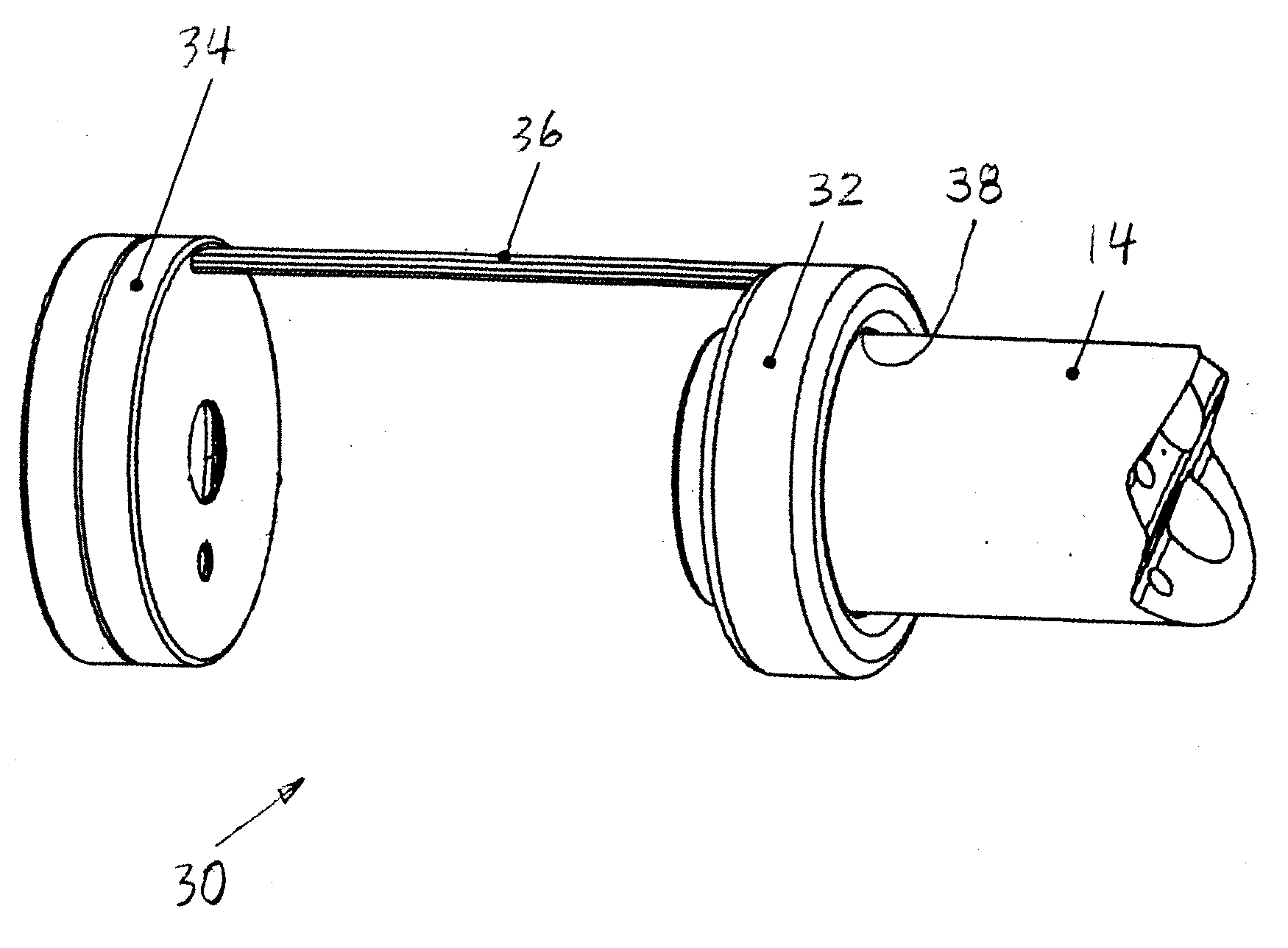
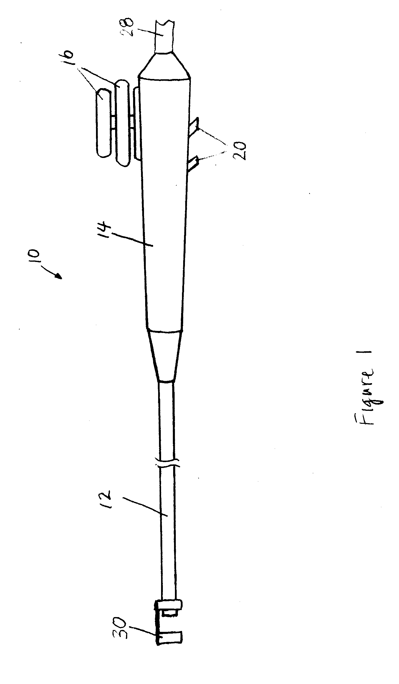
[0076]FIG. 14 illustrates additional embodiment 200 of the present invention that includes an insertion tube 212 and an attachment 232 mounted on the distal end region of the insertion tube 212. This attachment 232 may have some or all of features of the attachment 32 shown in FIGS. 3 and 5. Additionally, the attachment 232 is configured to accommodate one or more imaging units 242 and light sources 244 of the endoscope 200. In other words, the entire detachable imaging device 230 is mounted on the distal end region of the insertion tube 212 and does not extend beyond the distal end of the insertion tube 212. The imaging units 242 and light sources 244 may be mounted at any suitable locations on the attachment 232 and may be oriented in any directions. In this embodiment, the imaging units 242 and light sources 244 are placed on a proximal end of the attachment 232 and face backwards, although they may be alternatively or additionally placed on a distal end and / or side of the attach...
PUM
 Abstract
Description
Claims
Application Information
 - R&D
- Intellectual Property
- Life Sciences
- Materials
- Tech Scout
- Unparalleled Data Quality
- Higher Quality Content
- 60% Fewer Hallucinations
Browse by: Latest US Patents, China's latest patents, Technical Efficacy Thesaurus, Application Domain, Technology Topic, Popular Technical Reports.
© 2025 PatSnap. All rights reserved.Legal|Privacy policy|Modern Slavery Act Transparency Statement|Sitemap|About US| Contact US: help@patsnap.com


