
Filtering Face Mask with a Unidirectional Valve Having a Stiff Unbiased Flexible Flap

a filtering face mask and flexible flap technology, applied in the field of filtering face masks, can solve problems such as reducing wearer fatigue, and achieve the effects of reducing wearer fatigue, reducing effort, and reducing actuation power

Inactive Publication Date: 2007-06-28
3M INNOVATIVE PROPERTIES CO
View PDF50 Cites 44 Cited by
  • Summary
  • Abstract
  • Description
  • Claims
  • Application Information

AI Technical Summary

Benefits of technology

[0002] Persons who work in polluted environments commonly wear a filtering face mask to protect themselves from inhaling airborne contaminants. Filtering face masks typically have a fibrous or sorbent filter that is capable of removing particulate and / or gaseous contaminants from the air. When wearing a face mask in a contaminated environment, wearers are comforted with the knowledge that their health is being protected, but they are, however, contemporaneously discomforted by the warm, moist, exhaled air that accumulates around their face. The greater this facial discomfort is, the greater the chances are that wearers will remove the mask from their face to alleviate the unpleasant condition.
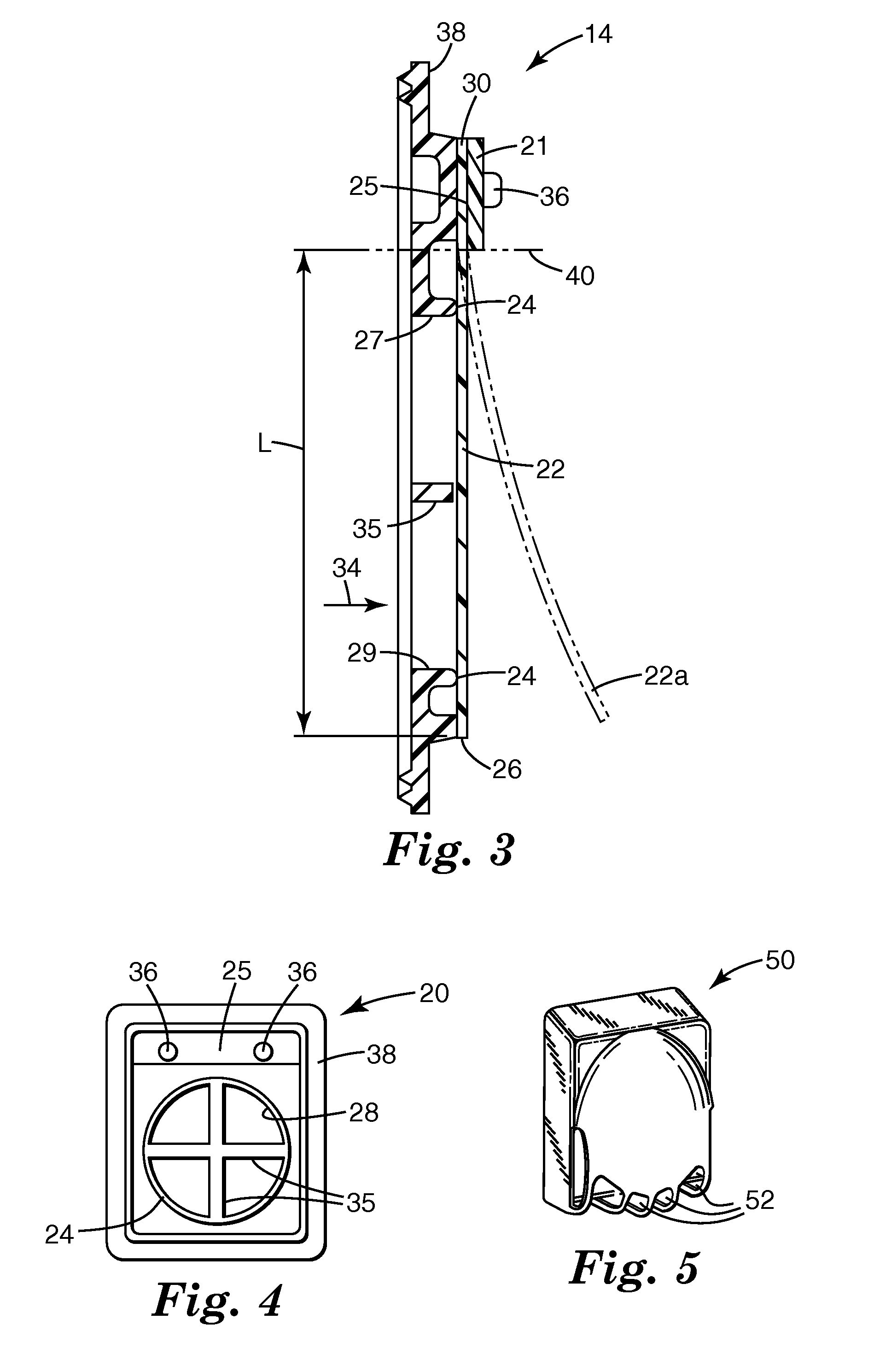
[0012] In some embodiments of cantilevered, flapper-style valves, the cantilever distance may be selected to reduce the actuation power required to open the valves. For example, the distance between the cantilevered edge along which the flap is supported and the orifice in the valve seat may be selected to increase the lever arm with which the force of fluid pressure operates to open the valve. The reduction in fluid pressure may reduce the effort required by a wearer to open the valve when breathing, thus potentially reducing the wearer's fatigue.

Problems solved by technology

The reduction in fluid pressure may reduce the effort required by a wearer to open the valve when breathing, thus potentially reducing the wearer's fatigue.

Method used


Image

  • Filtering Face Mask with a Unidirectional Valve Having a Stiff Unbiased Flexible Flap
  • Filtering Face Mask with a Unidirectional Valve Having a Stiff Unbiased Flexible Flap
  • Filtering Face Mask with a Unidirectional Valve Having a Stiff Unbiased Flexible Flap

Examples


example 1

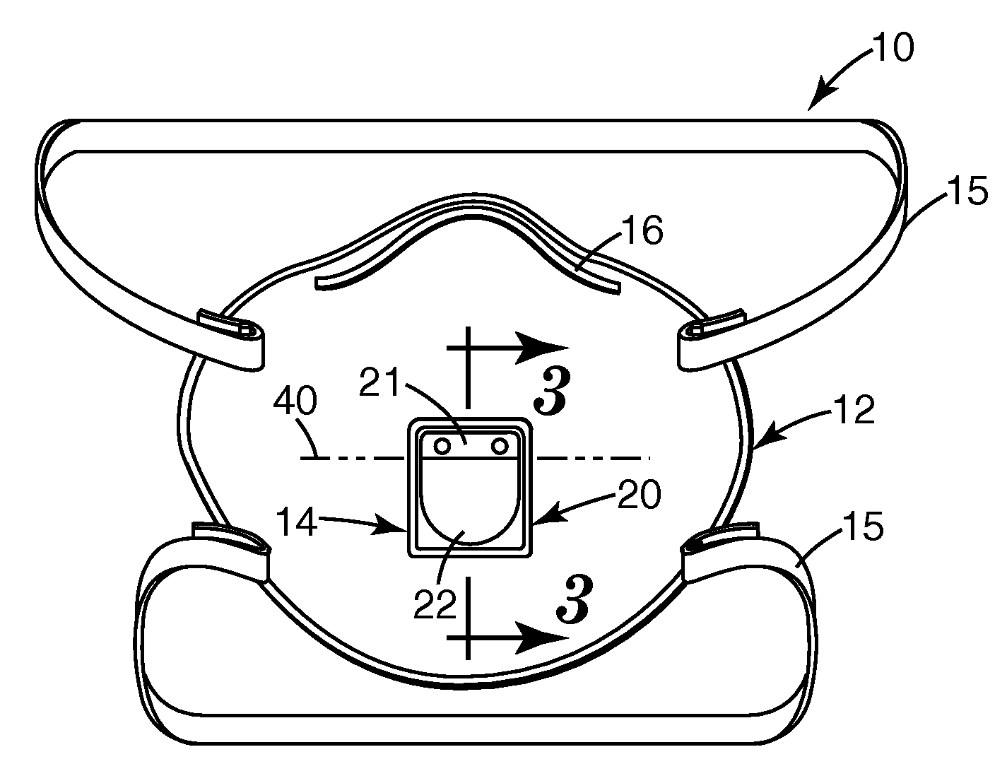
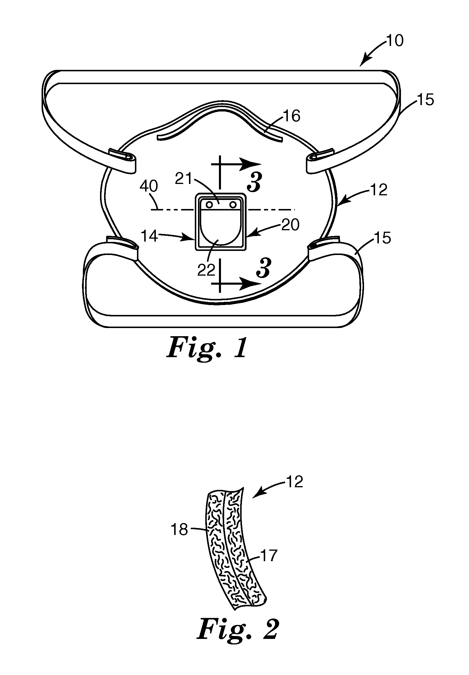
[0098] A flexible flap was formed from a sheet of nitrile rubber (1.969 mm thick, 60Shore A hardness) by die cutting the sheet to create a rectangular portion that had a semi-circular end (see FIG. 1, item 22). The overall length of the die-cut flap, including the semi-circular end, was about 3.1 cm, and the width of the flap was about 2.3 cm. The semi-circular end of the flap, in plan section, had a radius of 1.27 cm.

[0099] When measured according to the Cantilever Bending Ratio test described herein, the flap exhibited a deflection (d) of 25.4 micrometers with an extended length (L) of 2.14 cm for a d / L ratio of 0.0011.

[0100] To evaluate the leak rate performance of a valve incorporating this flap, the rectangular end of the flap was secured to a valve seat in a valve body using a flap hold-down with a length of 0.955 cm and a width that was coextensive with the flap width. The valve body had a valve seat that was flat or planar when viewed from a side elevation.

[0101] The conf...


PUM


Abstract

A filtering face mask that includes a mask body that is adapted to fit at least over the nose and mouth of a wearer to create an interior gas space when worn; and an exhalation valve that is in fluid communication with the interior gas space. The exhalation valve includes a valve seat with a seal surface and an orifice through which exhaled air may pass to leave the interior gas space; and a flexible flap that is mounted to the valve seat such that the flap makes contact with the seal surface when the valve is in its closed position and such that the flap can flex away from the seal surface during an exhalation to allow exhaled air to pass through the orifice. The flap is unbiased when in its closed position and exhibits a cantilever bend ratio of 0.0050 or less.

Description

[0001] The present invention pertains to a filtering face mask that uses a stiff, unbiased flexible flap as the dynamic mechanical element in an exhalation valve and / or an inhalation valve. [0002] Persons who work in polluted environments commonly wear a filtering face mask to protect themselves from inhaling airborne contaminants. Filtering face masks typically have a fibrous or sorbent filter that is capable of removing particulate and / or gaseous contaminants from the air. When wearing a face mask in a contaminated environment, wearers are comforted with the knowledge that their health is being protected, but they are, however, contemporaneously discomforted by the warm, moist, exhaled air that accumulates around their face. The greater this facial discomfort is, the greater the chances are that wearers will remove the mask from their face to alleviate the unpleasant condition. [0003] To reduce the likelihood that a wearer will remove the mask from their face in a contaminated env...

Claims


Application Information

Patent Timeline
IPC IPC(8): A62B18/08A62B23/02
CPCA62B18/025A62B18/10
Inventor MARTIN, PHILIP G.
Owner 3M INNOVATIVE PROPERTIES CO
Learn More