Switching device

Active Publication Date: 2007-06-28
ABB (SCHWEIZ) AG
View PDF7 Cites 5 Cited by
  • Summary
  • Abstract
  • Description
  • Claims
  • Application Information

AI Technical Summary

Benefits of technology

[0009] An advantage of the switching device according to the invention is that

Problems solved by technology

In addition to the electric arc being conductive, metal which has been vaporized from contacts by the electric arc may, upon solidification, impair the insulation capacity of the surfaces of the switching device.
Soot produced by the electric arc may also cause

Method used


Image

  • Switching device
  • Switching device

Examples


Example

[0007] An object of the invention is to provide a switching device to enable the above-described problem to be alleviated. The object of the invention is achieved by a switching device which is characterized by what is disclosed in the independent claim. Preferred embodiments of the invention are disclosed in the dependent claims.

[0008] The idea underlying the invention is that in its part remaining inside the frame, a connector of the switching device is equipped with a hole arranged for a gas flow.

[0009] An advantage of the switching device according to the invention is that disadvantages in a switching device caused by discharging gases are minimized.

DETAILED DESCRIPTION OF THE INVENTION

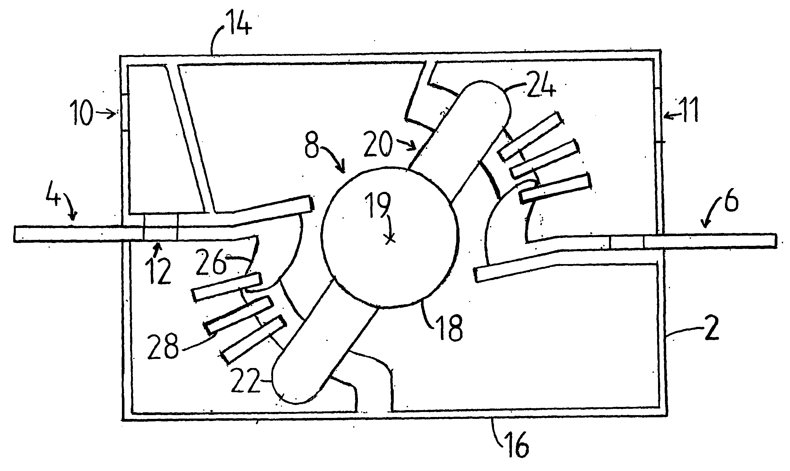
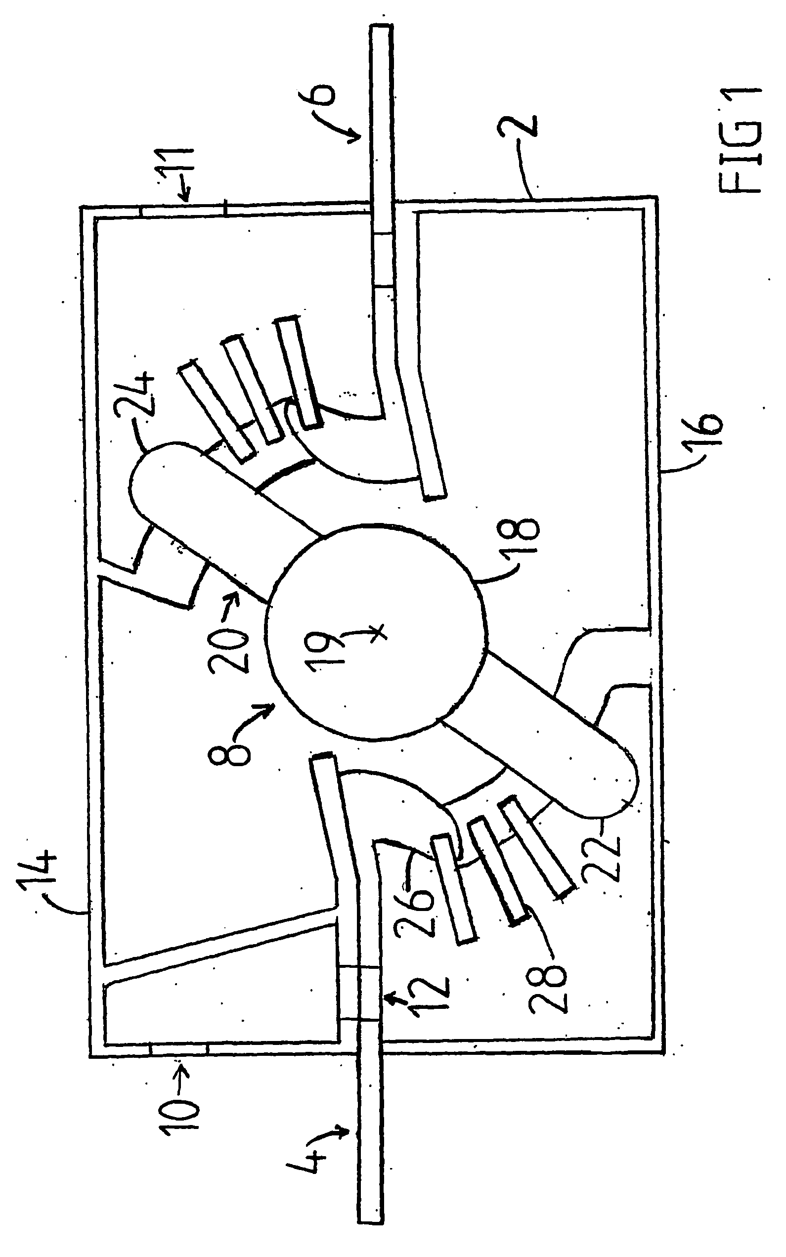
[0010] The invention is now described in closer detail in connection with the preferred embodiments and with reference to accompanying FIG. 1, which shows a cross-section of a switching device according to an embodiment of the invention. The switching device of FIG. 1 is in an open position, i....


PUM


Abstract

A switching device is disclosed which includes a frame, a first connector and a second connector, the first connector and the second connector extending from inside the frame outside the frame. The first and the second connector are electrically connected to one another, and one or more gas flow openings are provided in the frame and arranged for a gas flow produced by a switching event. In its portion remaining inside the frame, the first connector includes a hole provided for said gas flow.

Description

BACKGROUND OF THE INVENTION [0001] The invention relates to a switching device according to the preamble of the independent claim. [0002] Switching devices are equipment used for opening and closing a current circuit. A switching device comprises at least one pole and a control device arranged to open and close this pole. Switching devices include e.g. switches and switch-fuses. [0003] When a current circuit is opened, an electric arc whose temperature is thousands of degrees may occur in a switching device. An electric arc includes ionized gas which contains a large number of free electrons. Such a gas plasma is electrically conductive. [0004] In addition to the electric arc being conductive, metal which has been vaporized from contacts by the electric arc may, upon solidification, impair the insulation capacity of the surfaces of the switching device. Soot produced by the electric arc may also cause insulation problems. [0005] Switching devices wherein air is used as an insulating...

Claims


Application Information

Patent Timeline
IPC IPC(8): H01H33/66H01HH01H33/04H01H33/575
CPCH01H1/2041H01H9/342H01H77/10
Inventor PIKKALA, OSMOMATTLAR, HARRI
Owner ABB (SCHWEIZ) AG
Why Eureka
Try Eureka