

Clutch compensation piston
- Summary
- Abstract
- Description
- Claims
- Application Information
AI Technical Summary
Benefits of technology
Problems solved by technology
Method used
Image

Examples
first embodiment
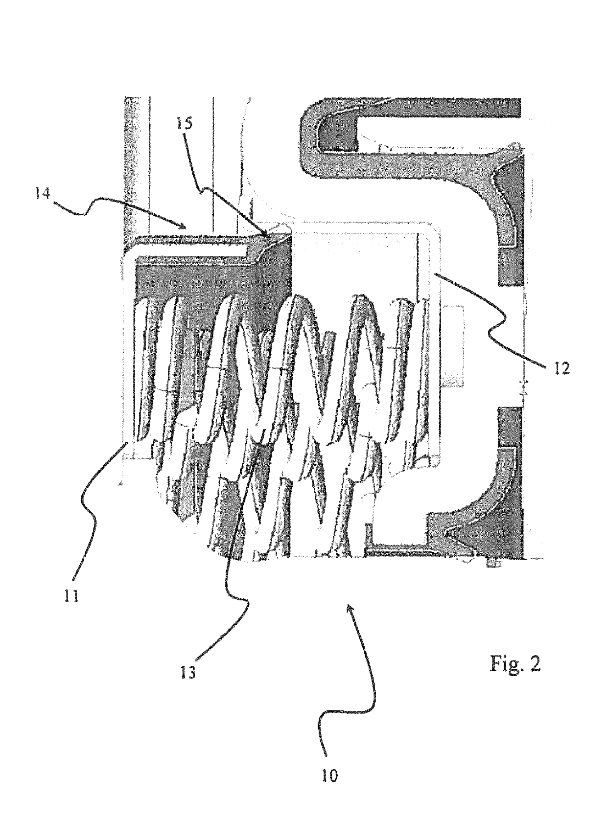
[0054]FIG. 2 shows the invention in a three-dimensional sectional view. A balance module 10 comprises a first piston part 11, a second piston part 12, a plurality of spring elements 13 and a sealing element 14 with a sealing lip 15. The elements 11-15 are connected to one another in a loss-proof manner, in order to form an integral balance module.
second embodiment
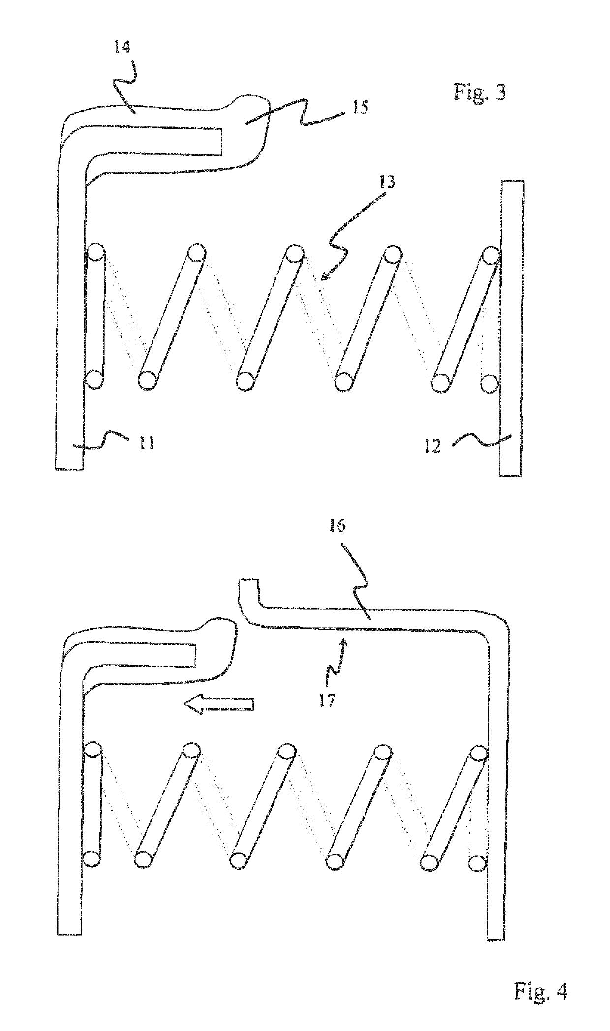
[0055]FIG. 3 shows the invention in cross section. In this design, the first piston part 11 is constructed with an essentially L-shaped cross section. The spring elements 13 are in this design attached, for example welded or adhesively bonded, both on the first piston part 11 and on the second piston part 12 in a loss-proof manner.
[0056]The sealing element 14, for example an injection moulded elastomer sealing element is attached on the horizontally running leg of the L cross section. The sealing element 14 has a radially outwardly projecting sealing 15. The second piston part 12 has a strip-shaped cross section in this design. An axial gap is present between the sealing lip 15 and the edge of the piston part 12 opposite the sealing lip. The geometry shown here means that the sealing lip runs on a part of the clutch or the gearbox in the installed state. This embodiment, which can be provided for example for restricted spatial conditions, is suitable for example to replace the left ...
third embodiment
[0057]FIG. 4 shows the invention in cross section in a non-installed state, similar to the embodiment of FIG. 3. Compared to the embodiment of FIG. 3, this embodiment has a differently constructed piston part 12, however. The piston part 12 is here provided with a running surface section 16, which is here formed as a leg of an essentially L-shaped cross section. The non-installed state is shown in this figure, in which the spring elements 13 are deflected to such an extent compared to the installation state (indicated by an arrow), so that there is an axial gap between the sealing lip and the edge (which is here illustrated as angled) opposite the sealing lip.
[0058]This embodiment, which can be provided for somewhat more generous spatial conditions, is for example suitable to replace the right balance piston in a gearbox as in FIG. 1.
[0059]FIG. 5 shows the embodiment of FIG. 4 in the installed state, in the non-actuated position. Here, the spring elements 13 are compressed to such a...
PUM
 Abstract
Description
Claims
Application Information