Asymmetrical bipolar voltage supply

Active Publication Date: 2019-03-05
IIE
View PDF6 Cites 0 Cited by
  • Summary
  • Abstract
  • Description
  • Claims
  • Application Information

AI Technical Summary

Benefits of technology

[0007]The problem addressed by the invention is that of developing an asymmetrical bipolar volta

Problems solved by technology

The simple solution due to the small number of semiconductor switches is here compared to the high

Method used


Image

  • Asymmetrical bipolar voltage supply
  • Asymmetrical bipolar voltage supply
  • Asymmetrical bipolar voltage supply

Examples


Example

[0031]The preferred embodiments of the present invention will now be described with reference to FIGS. 1-5 of the drawings. Identical elements in the figures are designated with the same reference numerals.

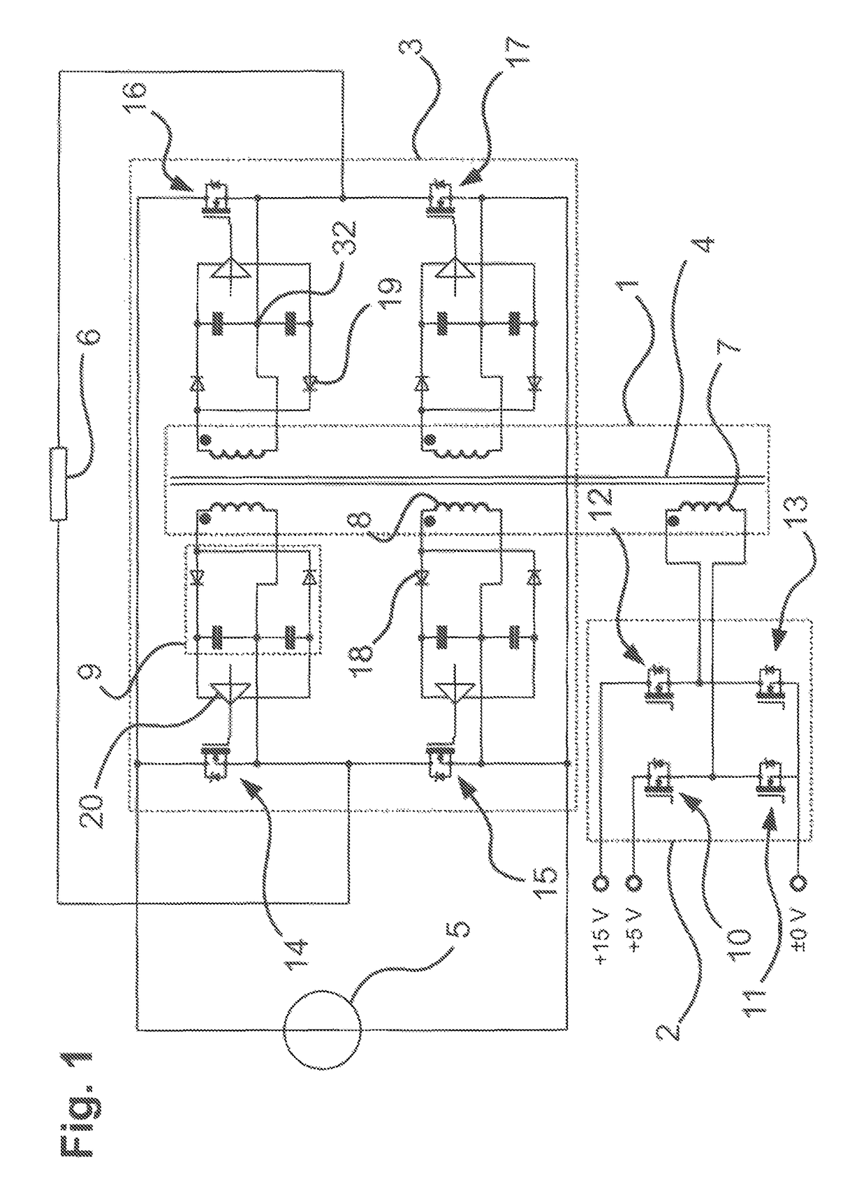
[0032]A bipolar power supply that supplies both a voltage of +15 V and a voltage of −5 V is often required for the gate control of modern fast semiconductor switches, such as SiC or GaN FETs. The invention will therefore be explained with reference to an embodiment of a respective asymmetrical bipolar voltage supply. FIG. 1 shows a schematic circuit diagram of such a voltage supply, in which the illustration of details that are not essential to the invention has been omitted.

[0033]The circuit has a transformer 1, which has a primary winding 7 and four secondary windings 8. A full-bridge circuit 2 that is formed by the four primary semiconductor switches 10 to 13 is provided on the primary-side of the transformer 1. The two legs of the full-bridge circuit 2 are supplied with differ...


PUM


Abstract

An asymmetrical bipolar voltage supply comprising a transformer (1), having at least one primary winding (7) and a plurality of secondary windings (8) and a primary-side power supply (2; 25; 28) connected to at least one DC voltage source. The circuit is configured and connected so as to generate in the transformer two oppositely polarized winding voltages UW1 and UW2 with different amplitudes.

Description

BACKGROUND OF THE INVENTION[0001]The invention concerns an asymmetrical bipolar voltage supply having a transformer with at least one primary winding and a plurality of secondary windings, and a primary-side power supply connected to the transformer.[0002]Modern power semiconductors that are to be used as semiconductor switches require an asymmetrical bipolar voltage supply of, for example, +15 and −5 volts for gate control. This is to prevent faulty switching. Such faulty switching can occur if the gate control is only set to zero potential in order to reach a switching state, and an interference is superimposed on this zero potential. In such a case, the semiconductor switch may begin to oscillate, which would quickly lead to its destruction. If, however, a voltage of −5 volts is applied, an interference cannot hinder the proper operation.[0003]To control the semiconductor switches of a full-bridge (also referred to as an H-bridge), four gate drivers are required with the technolo...

Claims


Application Information

Patent Timeline
IPC IPC(8): H02M1/08H02M3/335H02M7/5387H03K17/22H03K17/687
CPCH02M1/08H02M3/33569H03K17/687H03K17/223H02M7/5387H02M3/33573
Inventor KRESS, EKKEHARD
Owner IIE
Why Eureka
Try Eureka