
Supporting bracket for surveying instrument

a technology for supporting brackets and surveying instruments, which is applied in the direction of instruments, applications, signs, etc., can solve the problems of inability to securely and strongly fit each type of surveying instruments, and the post is made of plastic, and achieves the effects of hardly causing stains, high strength, and light weigh

Inactive Publication Date: 2007-06-28
SENSHIN KOGYO
View PDF7 Cites 6 Cited by
  • Summary
  • Abstract
  • Description
  • Claims
  • Application Information

AI Technical Summary

Benefits of technology

[0007] From such a viewpoint, it has been conceived to make a circular or elliptic post, which has a light weight and high strength and hardly causes stains owing to long-term use, of which manufacturing is easily performed and which can be provided at a low price, with use of plastic. However, it is impossible to securely and strongly fit each type of surveying instrument of various types on the market to such a post made of plastic. Thereupon, it is an object of the present invention to provide a supporting bracket capable of simply and securely fitting each type of surveying instrument to the post made of plastic, the post being light and low-priced, having high strength and hardly causing stains.
[0009] When each type of surveying instrument is supported by a post, the surveying instrument on the market is attached to the post by clamping it at the clamped portion of the supporting bracket and then the fitting portion of the supporting bracket is supported by the post. At this time, the fitting portion of the supporting bracket becomes capable of adjusting the fitting interval so that the supporting bracket can be fitted to the post made of plastic via the fitting portion, and therefore each type of surveying instrument can be fitted to the post to be vertically adjustable via the supporting bracket. The post made of plastic is light and low-priced, has high strength and hardly causes stains on the post, and therefore it is useful for surveying.
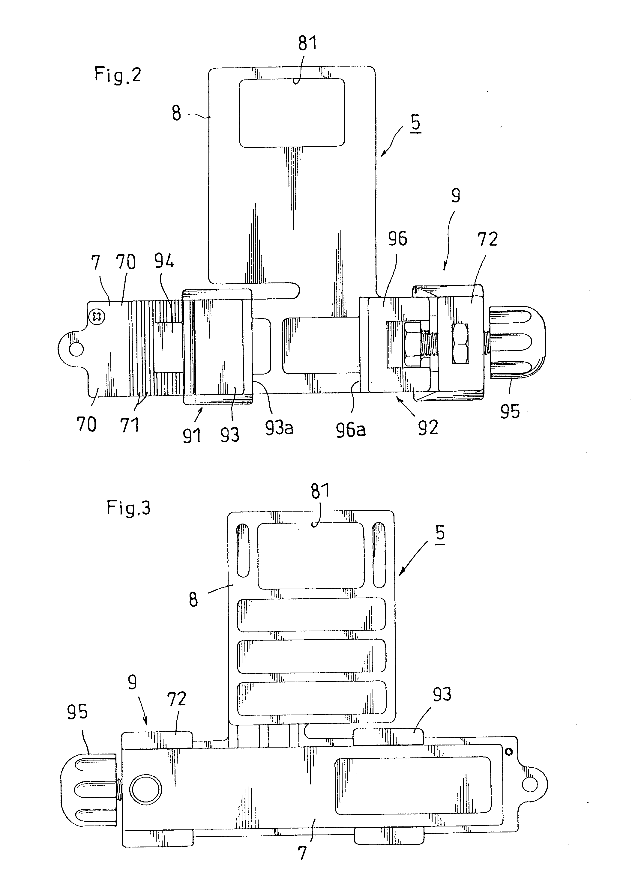
[0010] In an embodiment of the present invention, the fitting portion is comprised of a pair of a first clamping member and a second clamping member facing each other, the first and second clamping members are supported on a base table so as to be relatively displaceable. According to this constitution, adjustment of the fitting interval of the fitting portion can be easily performed. Thus, fitting each type of surveying instrument to the post and vertical adjustment of the surveying instrument become easy.
[0011] In another embodiment of the present invention, the first clamping member includes a first clamping piece supported to be movable along the base table and a claw portion slidably supported by the first clamping piece and capable of engaging with or disengaging from a plurality of steps of groove portions formed at the base table, and the second clamping member includes a second clamping piece movably supported by a screw body threaded into a part of the base table. According to this constitution, the first clamping piece is moved to a predetermined position to the base table while engaging or disengaging the claw portion with or from the groove portions of the base table, and the second clamping piece is movably adjusted to the first clamping piece via the screw body in this state. Therefore, adjustment of the fitting interval between the first and second clamping pieces can be securely performed, the supporting bracket can be simply and securely fitted to the post via these clamping pieces, and the vertical adjustment of the supporting bracket, or the surveying instrument, can be easily performed.
[0013] Further, in another embodiment of the present invention, it is possible to read graduations attached to the post fitted to the fitting portion, through a window formed in the clamped portion to which the surveying instrument is clamped. According to this constitution, though the surveying instrument is supported by the post via the supporting bracket, it is possible to confirm the graduations of the post, a height position of the surveying instrument fixed to the post from a soil level, etc., through the window of the clamped portion, and therefore it is convenient to perform a horizontal or gradient survey, etc.

Problems solved by technology

However, it is impossible to securely and strongly fit each type of surveying instrument of various types on the market to such a post made of plastic.

Method used


Image

  • Supporting bracket for surveying instrument
  • Supporting bracket for surveying instrument
  • Supporting bracket for surveying instrument

Examples


Embodiment Construction

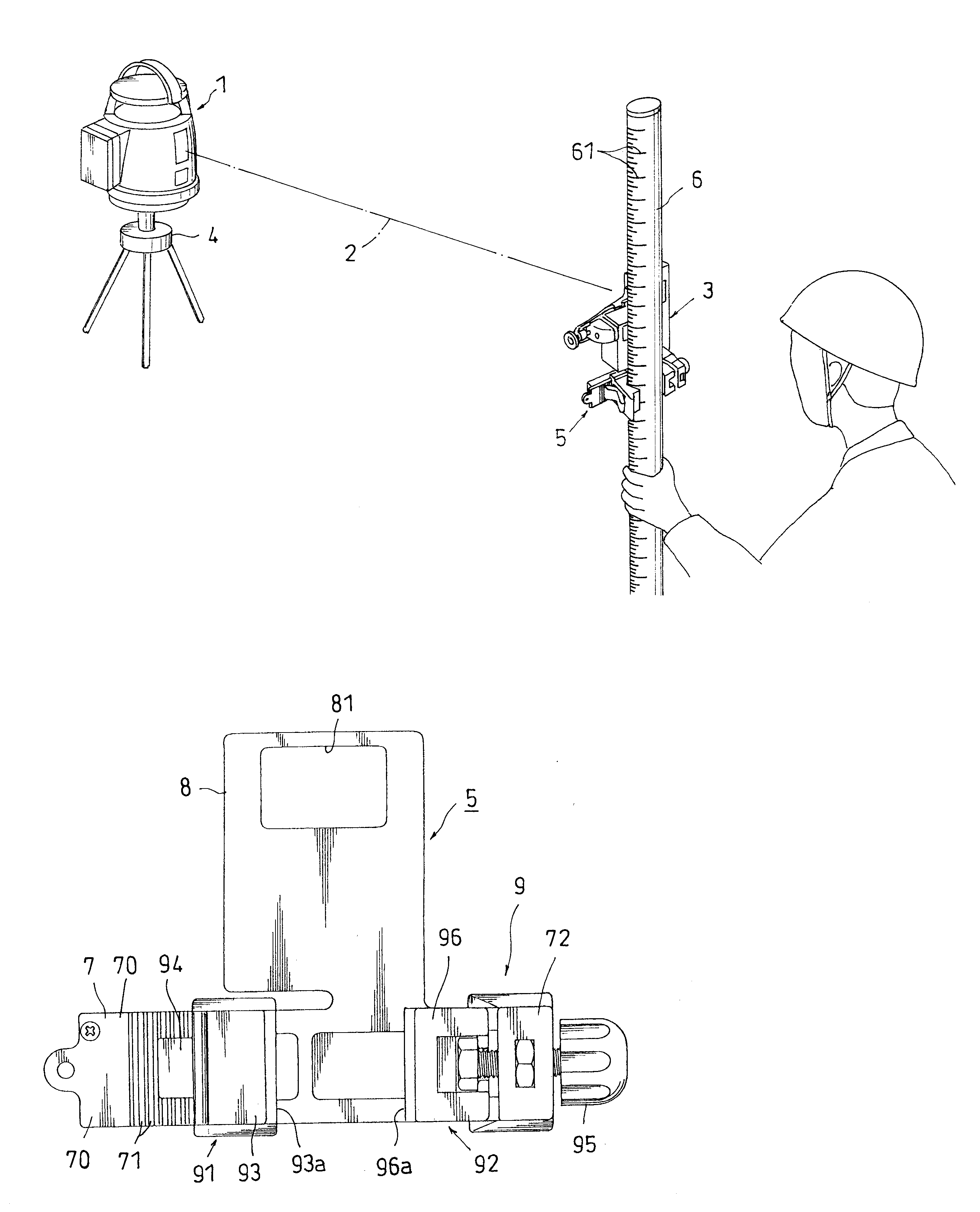
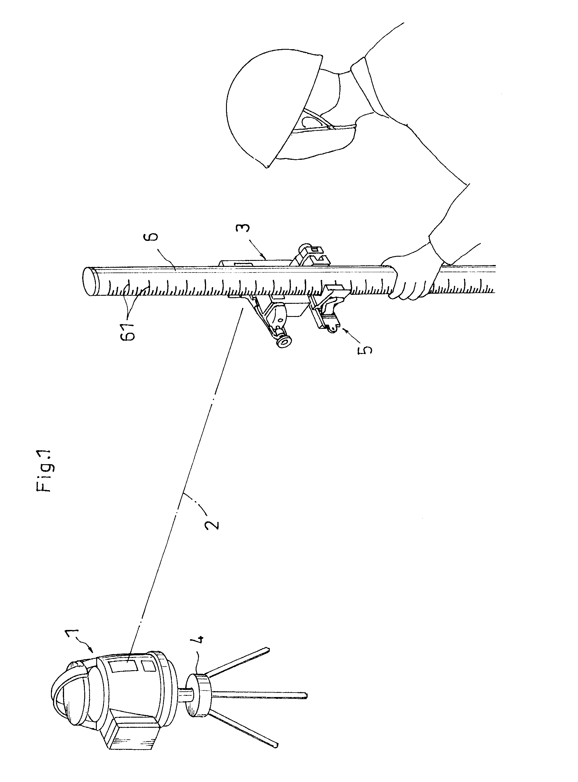
[0026] A supporting bracket for a surveying instrument according to the present invention will be explained below referring to the accompanying drawings. FIG. 1 is a perspective view showing a state where a horizontal or gradient survey is performed. In this figure, a laser transmitter 1 outputting a laser beam 2 and a receiver 3 as the surveying instrument receiving the laser beam 2 are used, the receiver 3 receives the laser beam 2 emitted from the transmitter 1 so that the horizontal or gradient survey is performed. The transmitter 1 is supported on a tripod 4, and the receiver 3 is supported by a post 6 via a supporting bracket5.

[0027]FIG. 2 is a front view showing the enlarged supporting bracket 5 according to the present invention, FIG. 3 is a rear view of the same, FIG. 4 is a plan view of the same, FIG. 5 is a bottom view of the same, FIG. 6 is a left side view of the same, FIG. 7 is a right side view of the same and FIG. 8 is a perspective view showing the whole supporting...


PUM


Abstract

A supporting bracket for a surveying instrument capable of simply and securely fitting each type of surveying instrument to a post 6 made of plastic, by use of the post 6 being light and low-priced, having high strength and hardly causing stains, wherein the supporting bracket 5 for supporting the surveying instrument 3 (receiver) with the post 6 includes a clamped portion 8 to which the survey instrument 3 is clamped to be supported, and a fitting portion 9 fitted to the post 6, and the fitting portion 9 can be fitted to an elliptic post, and a fitting interval to the post is adjustable.

Description

BACKGROUND OF THE INVENTION [0001] 1. Field of the Invention [0002] The present invention relates to a supporting bracket for supporting a surveying instrument with a post. [0003] 2. Description of the Related Art [0004] When a horizontal or gradient survey is performed, a laser transmitter and receiver are typically used, and the receiver is supported by a post so as to be vertically adjustable (see patent reference 1). Further, a metallic pipe made of aluminum, etc., is employed as the post, the post being formed in a cross-section rectanglar shape. [0005] Japanese Published unexamined Patent Application No. 2003-121149 [0006] Though conventional posts have been lightened by use of aluminum, etc., they have still been heavy. Further, stains such as rust caused by long-term use of a post made of aluminum, etc., make graduations attached to a surface of the post illegible. SUMMARY OF THE INVENTION [0007] From such a viewpoint, it has been conceived to make a circular or elliptic pos...

Claims


Application Information

Patent Timeline
Patent Type & Authority Applications(United States)
IPC IPC(8): G09F7/18
CPCG01C15/06
Inventor KIMURA, MASARU
Owner SENSHIN KOGYO
Learn More