Towing mechanism

Active Publication Date: 2007-06-28
DEERE & CO
View PDF13 Cites 9 Cited by
  • Summary
  • Abstract
  • Description
  • Claims
  • Application Information

AI Technical Summary

Benefits of technology

[0006] These and other objects are achieved by the present invention, wherein a towing mechanism includes an upper bracket spaced apart from a lower bracket for receiving a drawbar therebetween. The brackets have towing bolt bores therein for receiving a towing bolt, and a locking device releasably holding the towing bolt in the bores. The locking device includes a component with a pin bore extending therein for slidably receiving a locking pin. A spring is coupled to the locking pin. The locking device is mounted on the upper bracket so that the locking pin projects out of the pin bore and prevents an axial movement of the towing bolt.
[0007] The towing mechanism is provided with a structure or blocking member which prevents a foreign object from acting upon the locking pin, and thereby prevents an unintentional release of a trailer attached to the towing mechanism. Preferably, the blocking member is a projection on the towing bolt which at least partially (preferably completely) covers the cross sectional area of the pin bore or the end of the locking pin with respect to the longitudinal direction of the locking pin or the axis of the bore. In any case, the projection is configured so that, when the vehicle is moving backwards, the projection will prevent an object (such as a branch or a part of a fence) from contacting the locking pin. Alternatively, the blocking memb

Problems solved by technology

However, this spring is not designed to resist forces acting on the locking pin in the axial direction of the locking pin, such as caused by a foreign object.
I

Method used


Image

  • Towing mechanism
  • Towing mechanism
  • Towing mechanism

Examples


Example

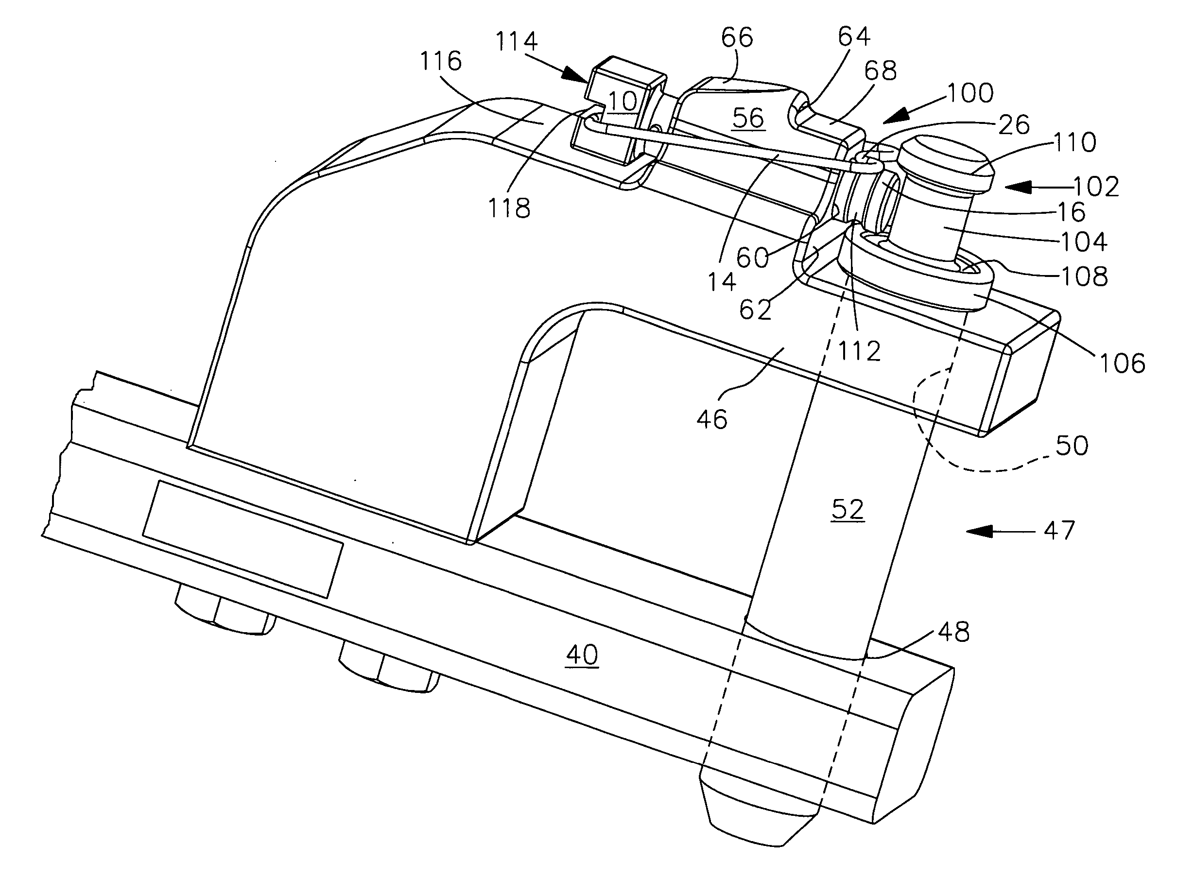
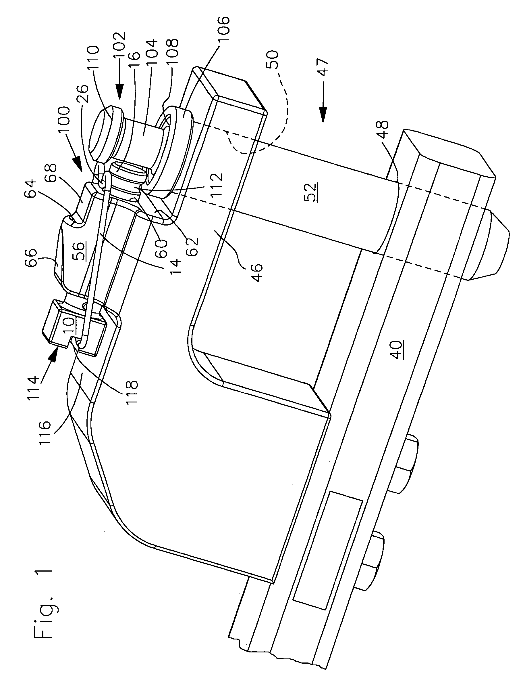
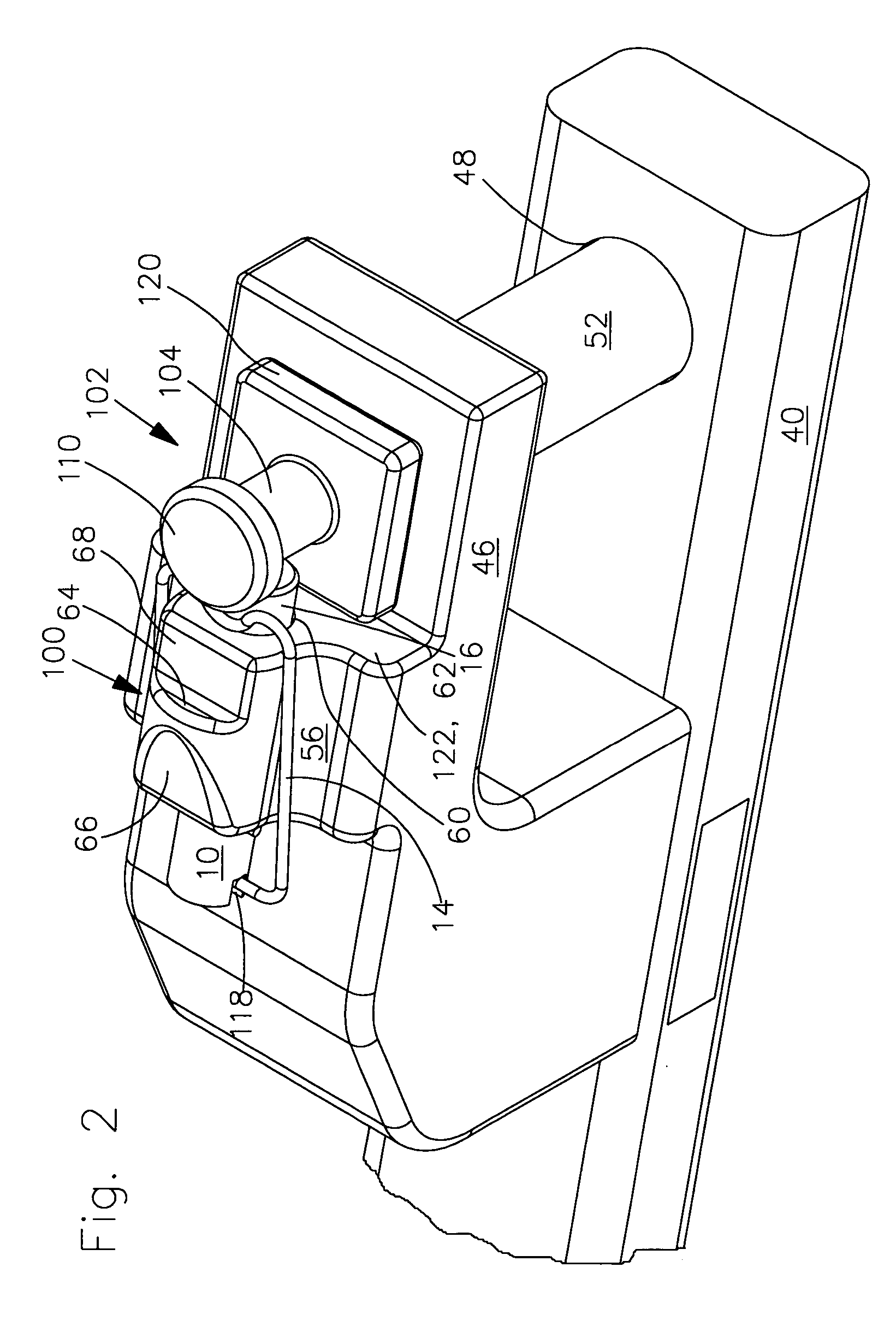
[0013] The towing mechanism of FIG. 1 includes a lower bracket 40 with a locating bore 48 and an upper bracket 46 with a locating bore 50. A towing bolt 52 can be inserted into the locating bores 48, 50, in order to retain or couple to a drawbar (not shown) of a trailer (not shown). The left end (not shown) of the towing mechanism may be pivotally coupled to a vehicle (not shown). The upper bracket 46 is bolted to lower bracket 40.

[0014] The towing mechanism also includes a locking device 100. Locking device has a locking pin 10 and a spring 14 with a loop 26. The pin 10 has a cylindrical shaft section 16 that can be inserted into a bore 60 in component 56. An end of the shaft section has a chamfer in order to simplify its insertion into the bore 60. The locking pin may be configured as shown in U.S. Pat. No. 7,048,294, which is herein incorporated by reference.

[0015] The component 56 is fastened to the upper surface of the upper bracket 46, such as by bolting or welding. Or, the ...


PUM


Abstract

A towing mechanism includes a pair of brackets for receiving a drawbar therebetween, and a locking device. A towing bolt is received by locating bores in the brackets. The locking device includes a locking pin which is axially slidable in a pin bore in a component. The locking device is mounted on the upper bracket so that, in a locked condition, the locking pin projects out of the bore and prevents axial movement of the towing bolt. A blocking member at least partially covers the pin bore and prevents the extraneous material from contacting the locking pin, in order to reduce the likelihood of an unintentional release of the towing bolt.

Description

FIELD OF THE INVENTION [0001] The invention relates to a towing mechanism with an upper bracket, a lower bracket and a locking device. BACKGROUND OF THE INVENTION [0002] A known towing mechanism is shown in U.S. Pat. No. 7,048,294, which issued in May 2006 and which is assigned to the assignee of this application. This mechanism is designed for use with a utility vehicle, such as an agricultural tractor. This known towing mechanism includes an upper bracket, a lower bracket and a locking device. Such lower brackets are also referred to as tractor drawbars, and such upper bracket are referred to as a hammerstrap. [0003] An implement drawbar is received between the two brackets and retained by a towing bolt which is received in bores in the brackets. The locking device includes a locking pin which slides axially in a pin bore. The locking pin projects from the pin bore and engages and prevents axial movement of the towing bolt. The locking pin includes a loop-shaped spring which preve...

Claims


Application Information

Patent Timeline
IPC IPC(8): B60D1/60
CPCB60D1/02B60D1/025F16B21/12
Inventor HEITLINGER, MARTINPATINO, MARIO
Owner DEERE & CO
Why Eureka
Try Eureka