Electrofusion socket forming system

a technology of electrofusion socket and forming system, which is applied in the direction of pipe elements, heating element shapes, heating elements, etc., can solve the problems of short circuit, loss of power, and end of electrofusion joint formation

Inactive Publication Date: 2007-06-28
KARL HEINZ KRAH
View PDF48 Cites 8 Cited by
  • Summary
  • Abstract
  • Description
  • Claims
  • Application Information

AI Technical Summary

Benefits of technology

[0007] Surprisingly, it has been found that provision of an electrofusion joint assembly including a meltable member and a heating element attached to the meltable member by at least one fastener in accordance with the present invention prevents substantial movement of the heating element during formation of the electrofusion joint.
[0008] In accordance with one embodiment of the present invention, an electrofusion joint assembly is provided including a first pipe having a spigot end, a second pipe having a bell end for receiving the spigot end of the first pipe, a heating element embedded in either the spigot end of the first pipe or in the bell end of the second pipe for creating a melt zone proximal the heating element when supplying the heating element with power, and at least one fastener extending through a meltable zone and into a non-melt zone of the embedded end of the pipe for securing the heating element in the embedded end of the pipe to prevent substantial movement of the heating element when supplying the heating element with power for making the electrofusion joint.
[0009] In still another embodiment, an electrofusion joint assembly is provided including a first pipe and a second pipe to be connected, a fitting having first and second ends adapted for receiving the first and second pipes, a heating element embedded in each of the first and second fitting ends for creating a melt zone proximal the heating element when supplying the heating element with power, and at least one fastener extending through a meltable zone and into a non-melt zone of the fitting for securing the heating element in the first and second ends of the fitting to prevent substantial movement of the heating elements when supplying the heating elements with power for making the electrofusion joint.
[0010] In still another embodiment, a method of making an electrofusion joint is provided including providing a first pipe having a spigot end, providing a second pipe having a bell end, embedding a heating element and a plurality of fasteners in either the spigot end of the first pipe or in the bell end of the second pipe, the at least one fastener extending through a meltable zone and into a non-melt zone of the embedded pipe, inserting the spigot end of the first pipe into the bell end of the second pipe, creating a melt zone proximal the heating element by supplying power to the heating element, the heating element being prevented from substantially moving when creating the melt zone by the at least one fastener extending through the melt zone and into the non-melt zone of the embedded pipe; and terminating the supply of power to the heating element to fuse the first and second pipes together.
[0011] In another embodiment of the present invention, a second member has a tapered end for receiving a first member. The inner surface of the second member and the outer surface of the first member are substantially non-parallel. A ring positioned around the outer surface of the second member compresses the second member proximal the first member, thereby eliminating poor joint make-up due to variations in pipe sizes due to allowable tolerances.
[0012] In a further embodiment of the present invention, multiple power sources are used to form the electrofusion joint. Separate heating elements are each powered by an individual power source, thereby reducing weld time and avoiding breakdown of the electrical circuit that may cause poor electrofusion weld joints, particularly in large diameter pipe.

Problems solved by technology

During such movement, one portion of the heating element may come into contact with another portion causing the circuit to short out.
A short circuit causes loss of power to the heating element, thereby prematurely ending formation of the electrofusion joint.
This results in a weak joint between the two pipe members.
Movement of the heating element becomes more pronounced, and thus a larger problem, with increasing pipe diameter.
In addition, when joining pipe using electrofusion, difficulties are encountered in preparing the pipe for the welding process due to the variation in tolerances encountered in pipe diameters.
The variation in pipe diameters may lead to a bell end of a first pipe having an inner diameter too small to receive a second pipe, or, alternatively, the bell end of a first pipe having an inner diameter too large to form a proper fit with the socket end of a second pipe, such that a bad joint is formed.
This problem becomes more pronounced as pipe diameters increase since variation in the range of pipe size tolerances increases with pipe diameter.

Method used


Image

  • Electrofusion socket forming system
  • Electrofusion socket forming system
  • Electrofusion socket forming system

Examples


Embodiment Construction

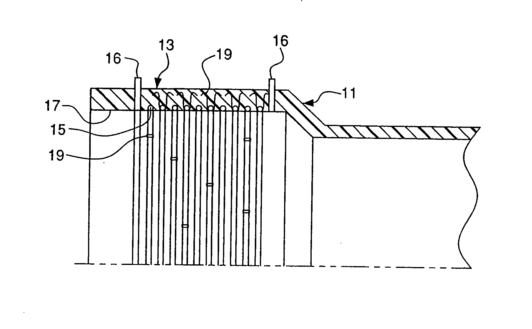
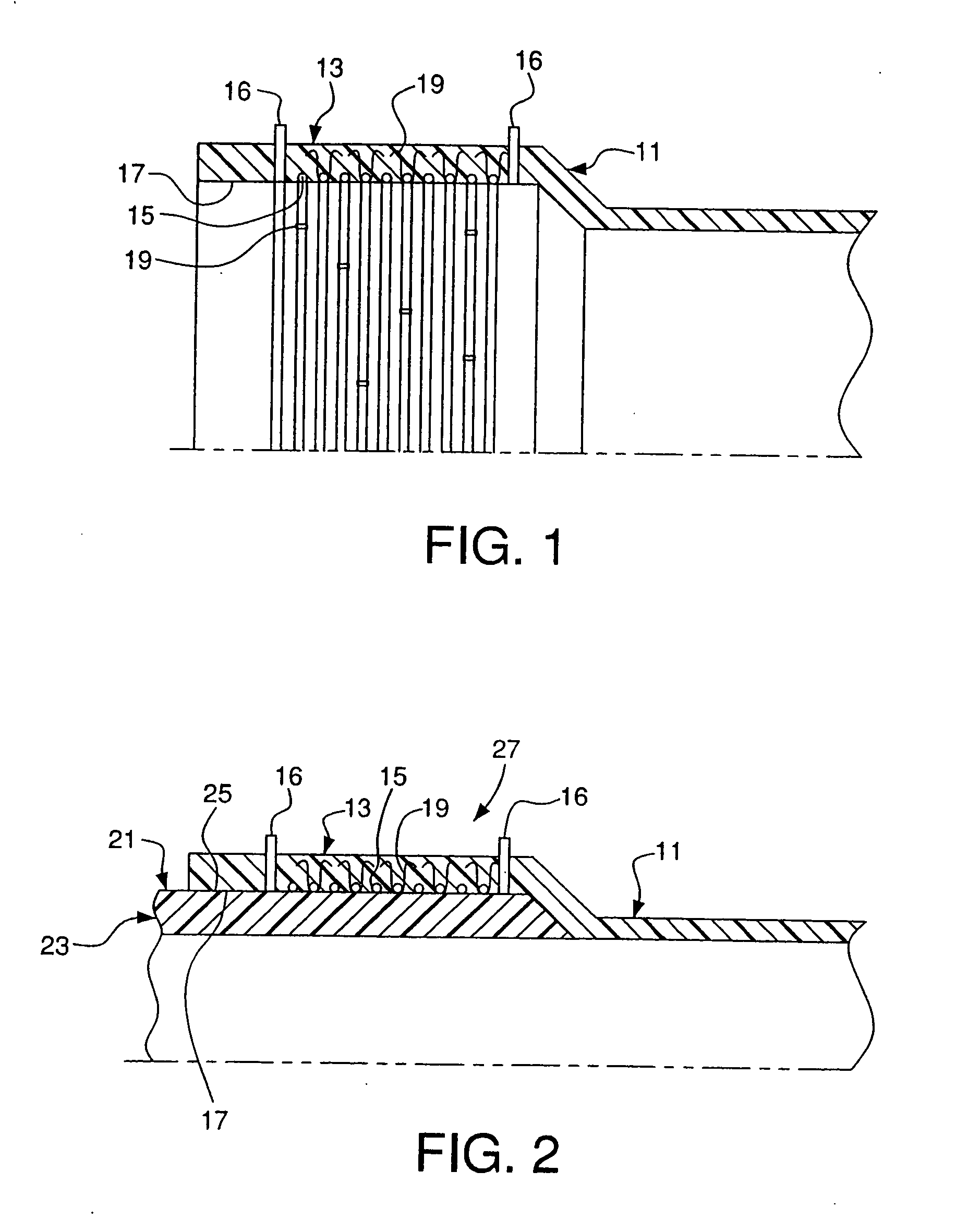
[0033] As seen in FIGS. 1-16, the present invention relates to assemblies for and methods of making an electrofusion weld joint. A meltable member, such as a pipe member as shown in FIG. 1 or a double socket fitting as shown in FIG. 11, has a heating element and at least one fastener attaching the heating element to the meltable member. The meltable member may be a pipe, fitting or any other suitable member in which the heating element is to be embedded. Preferably, the meltable member is a thermoplastic. The methods and assemblies described herein may be used to create an electrofusion weld joint for pipe of any diameter. Preferably, meltable members having diameters of eighteen inches and larger are used to make an electrofusion joint.

[0034] As shown in FIG. 1, a bell portion 13 of a pipe 11 has a heating element 15 embedded therein. Preferably, the heating element 15 is embedded from the inner surface 17 of the bell portion 13 of the pipe 11. At least one fastener 19 is used to ...


PUM

PropertyMeasurementUnit
diametersaaaaaaaaaa
taper angleaaaaaaaaaa

Abstract

An electrofusion joint assembly includes a meltable member, such as a pipe or fitting, and a heating element secured to the pipe or fitting. The pipe or fitting may be tapered to facilitate receiving another pipe to form an electrofusion weld joint. Fasteners are used to secure the heating element and extend through a meltable zone and into a non-melt zone. Power supplied to the pipe melts the pipe proximal the heating element.

Description

CROSS-REFERENCE TO RELATED APPLICATIONS [0001] This application is a continuation application of Ser. No. 10 / 861,489, filed Jun. 7, 2004, which, in turn, is a divisional application of Ser. No. 09 / 935,337, filed Aug. 23, 2001 (now U.S. Pat. No. 6,781,099), which claims the benefit under 35 U.S.C. § 119(e) of provisional application Ser. No. 60 / 274,661, filed Mar. 12, 2001, which are hereby incorporated by reference in their entirety.FIELD OF THE INVENTION [0002] The invention relates to an assembly for and a method of making an electrofusion joint including a meltable member having a heating element. BACKGROUND OF THE INVENTION [0003] Electrofusion joints have been developed and used for joining pipe used in a variety of applications, such as sewage system piping. Typically, when joining two pipes directly together using an electrofusion joint, one end of a first pipe has a heating element embedded therein. A second pipe is then inserted into the end of the first pipe in which the h...

Claims


Application Information

Patent Timeline
Patent Type & Authority Applications(United States)
IPC IPC(8): F16L47/02B29C65/00B29C65/34F16L47/03
CPCB29C65/342B29C65/3432B29C65/7841B29C66/303B29C66/3034B29C66/5221B29C66/5229B29C66/52292B29C66/63B29K2101/12F16L47/03B29C66/116B29C65/00B29C65/3468B29C65/3428B29C65/3476B29C66/52298B29C66/1222B29C66/1224B29C66/1226B29C66/1122
Inventor KRAH, KARL-HEINZ
Owner KARL HEINZ KRAH
Why Eureka
Try Eureka