
Ultrasonic motor

a technology of ultrasonic motors and motors, applied in piezoelectric/electrostrictive/magnetostrictive devices, piezoelectric/electrostriction/magnetostriction machines, electrical apparatus, etc., can solve the problems of increasing the manufacturing cost of ultrasonic motors, processing costs become significantly higher, and the failure to achieve ultrasonic motors that provide higher rotation efficiency, etc., to achieve the effect of higher rotation efficiency of the rotor

Inactive Publication Date: 2007-06-28
RICOH IMAGING COMPANY
View PDF8 Cites 12 Cited by
  • Summary
  • Abstract
  • Description
  • Claims
  • Application Information

AI Technical Summary

Benefits of technology

[0008] Aspects of the invention provide an ultrasonic motor in which a stator and a rotor are more closely butted to each other so as to achieve higher rotation efficiency of the rotor.

Problems solved by technology

In an actual manufacturing process of the ultrasonic motor, however, it is practically difficult to satisfy such requirements, and hence a conversion loss into the rotating motion of the rotor 2 is inevitably incurred, thus resulting in failure in achieving an ultrasonic motor that provides higher rotation efficiency.
It may be technically possible to upgrade the surface accuracy, however in this case the processing cost becomes significantly higher, which naturally leads to an increase in manufacturing cost of the ultrasonic motor.
The technique according to '266 publication of elastically deforming the comb teeth of the stator in the rotation direction of the rotor is, however, not applicable to the ultrasonic motor as shown in FIG. 11, in which the comb teeth are circumferentially displaced to transmit the rotational force to the rotor.
Even when the technique according to '266 publication is somehow applicable, the press-contact between the comb teeth and the rotor inevitably becomes uneven when the surface accuracy in a radial direction of the comb teeth and the rotor is insufficient, because the comb teeth are not designed to be elastically deformed radially.
Consequently, the rotation efficiency cannot be improved as desired.

Method used


Image

  • Ultrasonic motor
  • Ultrasonic motor
  • Ultrasonic motor

Examples


first embodiment

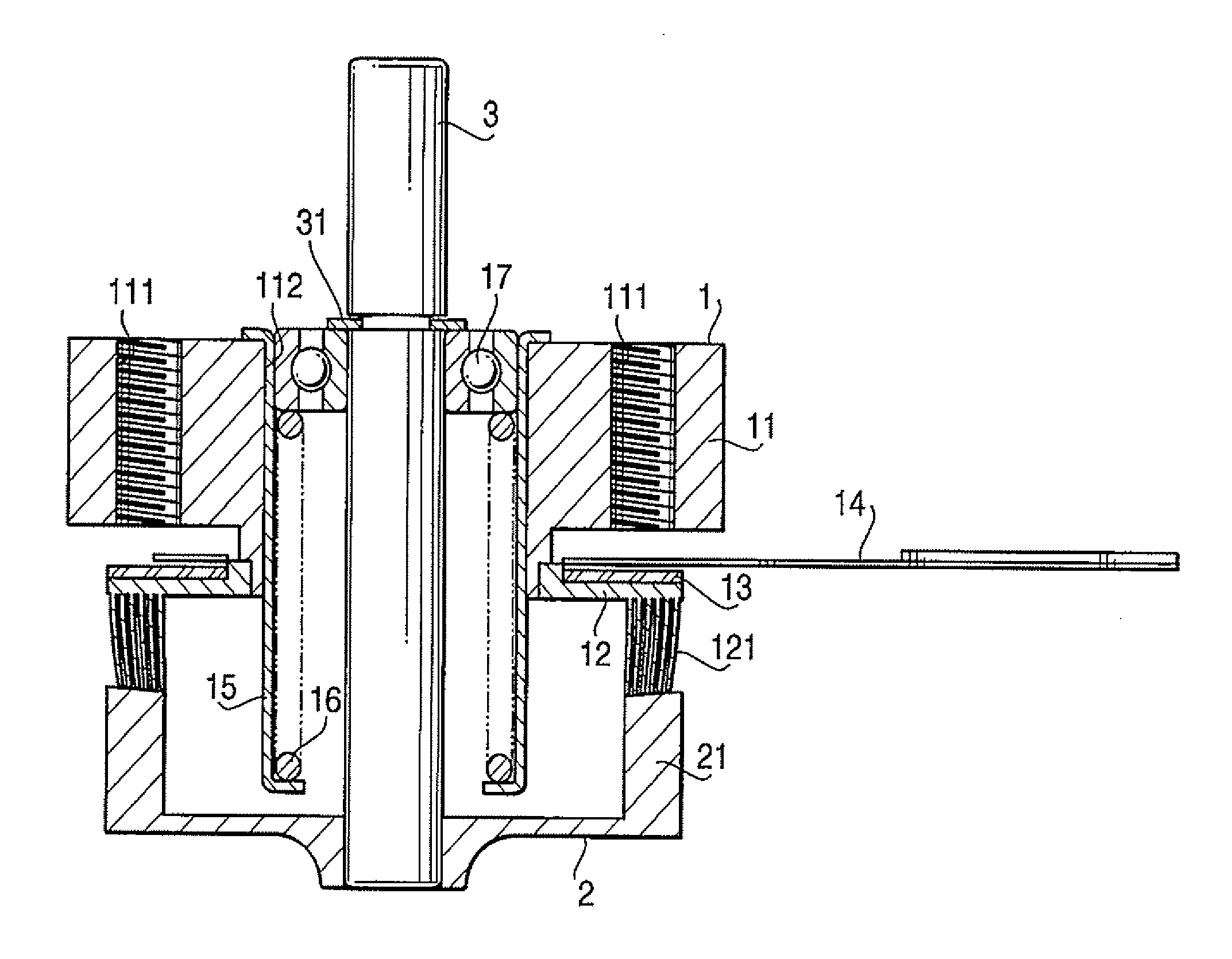
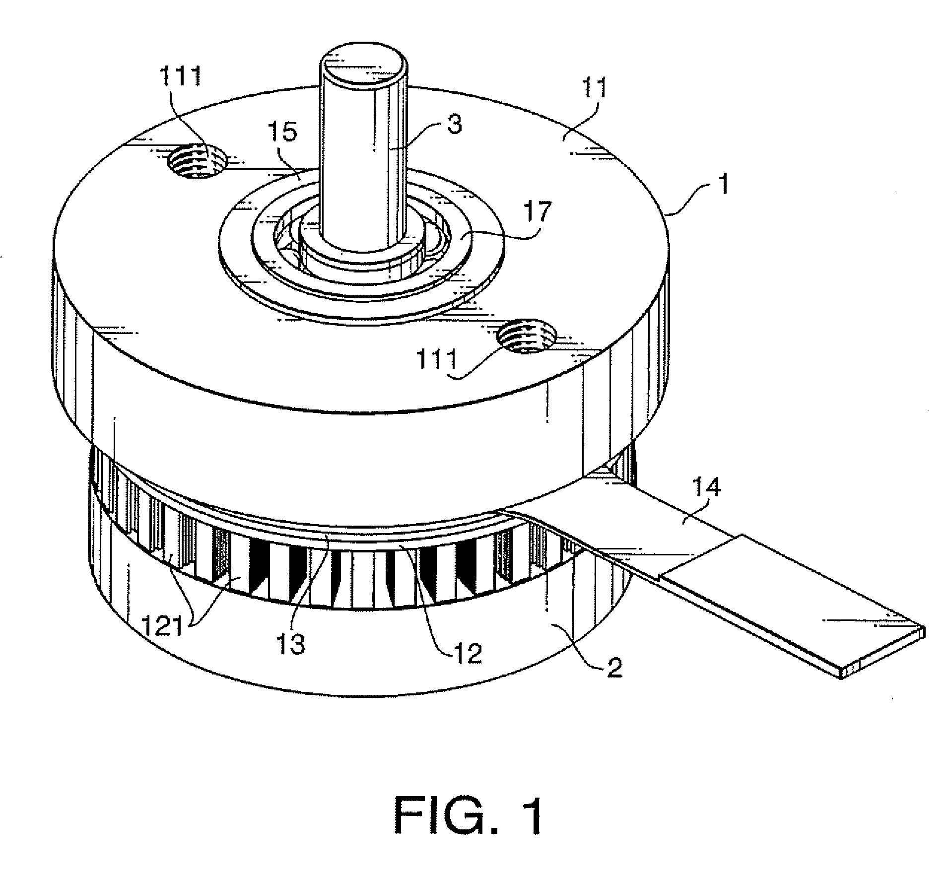
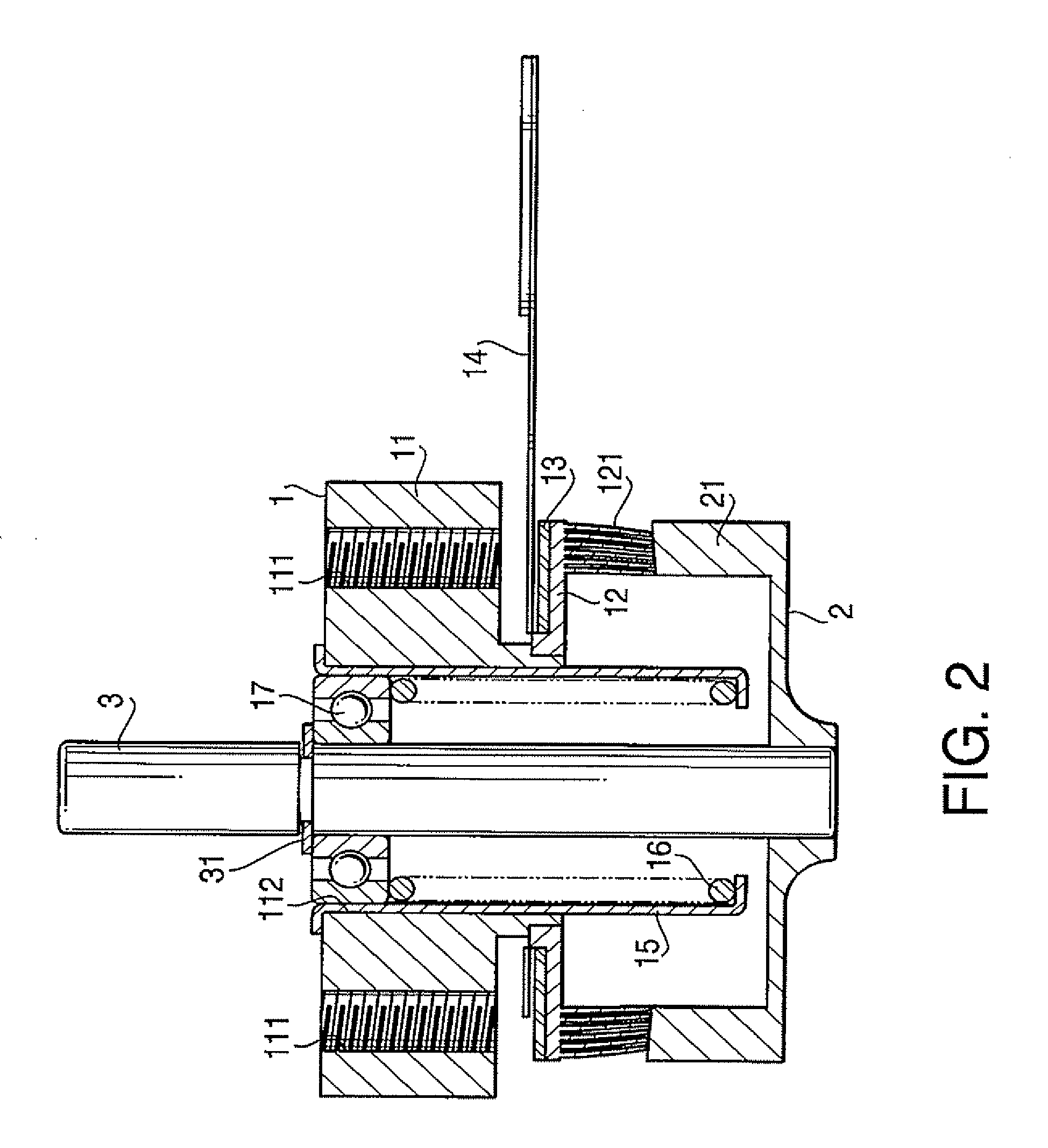
[0024] Hereunder, an embodiment of the present invention will be described referring to the drawings. FIG. 1 is a perspective view showing an appearance of an ultrasonic motor FIG. 2 is a vertical cross-sectional view of the ultrasonic motor shown in FIG. 1, and FIG. 3 is an exploded perspective view of a part of the ultrasonic motor. In these drawings, a short cylindrical container-shaped comb teeth body 12 with a plurality of comb teeth 121 circumferentially aligned thereon is integrally attached to a lower face of a disk-shaped base 11 with a mounting hole 111 for the motor, and a flat disk-shaped piezoelectric element 13, circumferentially polarized in a plurality of magnetic poles respectively corresponding to the comb teeth 121, is integrally mounted on an upper face of the comb teeth body 12, and the piezoelectric element 13 and the comb teeth body 12 constitute the stator 1. To the piezoelectric element 13, a high frequency voltage is to be applied via a flexible substrate ...

embodiment 1

[0027] In the ultrasonic motor when a high frequency voltage is applied to the piezoelectric element 13 via the flexible substrate 14, the piezoelectric element 13 vibrates, and hence the comb teeth body 12 integrally mounted thereon vibrates, to thereby circumferentially displace the plurality of comb teeth 121 which are circumferentially aligned, i.e. each group of the six pieces of pin-shaped elements 122. Since the peripheral wall portion 21 of the rotor 2 is pressed by the spring force of the compressed coil spring 16 against the tip portion 122a of the respective pin-shaped elements 122, i.e. to the press-contact surface, the peripheral wall portion 21 of the rotor 2 is circumferentially moved by the frictional force created on the press-contact surfaces of the peripheral wall portion 21 of the rotor 2 and the pin-shaped elements 122, so that the rotor 2 and the rotating shaft 3 integrally attached thereto are caused to rotate. The rotational force of the rotating shaft 3 is ...


PUM


Abstract

An ultrasonic motor is provided with a circular stator including a piezoelectric element and a comb teeth body with a multitude of comb teeth circumferentially aligned thereon, and a circular rotor supported by a rotating shaft and pressed against the comb teeth body, wherein the comb teeth respectively include, at least in a portion thereof press-contacting the rotor, a plurality of pin-shaped elements radially aligned at a predetermined interval. The pin-shaped element is elastically deformable in a radial direction at least in a tip portion thereof, and has a predetermined rigidity in a circumferential direction.

Description

BACKGROUND OF THE INVENTION [0001] The present invention relates to an ultrasonic motor, and more particularly to an ultrasonic motor with improved rotation efficiency with respect to amount of power supplied thereto. [0002] An ultrasonic motor includes a stator on which a piezoelectric element polarized in a plurality of magnetic poles is circumferentially disposed, and a disk-shaped or ring-shaped rotor rotatably butted to the stator at a predetermined pressure, and is configured to apply a high frequency voltage to the piezoelectric element of the stator to cause the piezoelectric element to vibrate, and to circumferentially expand the vibration with the comb teeth body integrally provided with the piezoelectric element for circumferentially moving the comb teeth body in a traveling wave form, thus to cause the rotor, which is frictionally engaged with the piezoelectric element, to rotate around the shaft. [0003]FIG. 11 is a cross-sectional view showing an example of a convention...

Claims


Application Information

Patent Timeline
Patent Type & Authority Applications(United States)
IPC IPC(8): H02N2/00
CPCH02N2/0065H02N2/163
Inventor KUROSAWA, YUICHI
Owner RICOH IMAGING COMPANY
Learn More