Position input device and computer system

a technology of position input and input device, which is applied in the field of battery-free position pointing, can solve the problems of increasing power consumption of position detector device, affecting the accuracy of detecting position, and unnecessary transmission of signals from position detector device, so as to reduce power consumption of position pointing device, improve accuracy of detecting position, and reduce battery change and recharge frequency

Inactive Publication Date: 2007-06-28
WACOM CO LTD
View PDF23 Cites 158 Cited by
  • Summary
  • Abstract
  • Description
  • Claims
  • Application Information

AI Technical Summary

Benefits of technology

[0011] Aspects of this invention were devised in light of the above circumstances, and certain aspects have as an object the provision of a position indicator device capable of stable position detection without readily being affected by external noise even under low power consumption, which is lightweight, and which does not require battery replacement. It is another object of the invention to provide a position input system and a computer system to which this position indicator device is applied.

Problems solved by technology

However, strengthening of the signals is problematic inasmuch as power consumption by the position detector device is increased.
It has been proposed to incorporate a battery into the position indicator, so that the transmission of signals from the position detector device becomes unnecessary.
However, the use of batteries can also raise problems.
In the case of the above-described position indicator, replacing the battery is time consuming and troublesome.
Also, if the intensity of signals transmitted from the position indicator is to be increased, power consumption is increased and battery depletion occurs in a short length of time, so that the batteries built into the position indicator may need to be replaced frequently, causing further inconvenience.
In addition, the weight of a position indicator incorporating a battery is increased significantly, and there is the further problem that operating properties are severely degraded.
However, if a position pointing device possesses a built-in power supply unit (i.e., a battery) and a plurality of oscillation units instead of the above-discussed tuning circuits, then power consumption of the built-in power supply unit is increased by a multiple equal to the number of oscillation units in the position pointing device, e.g., if the position pointing device contains two oscillation units, then power consumption is doubled.
As a result, the battery must be replaced or recharged more frequently, inconveniencing the operator.

Method used


Image

  • Position input device and computer system
  • Position input device and computer system
  • Position input device and computer system

Examples


first embodiment

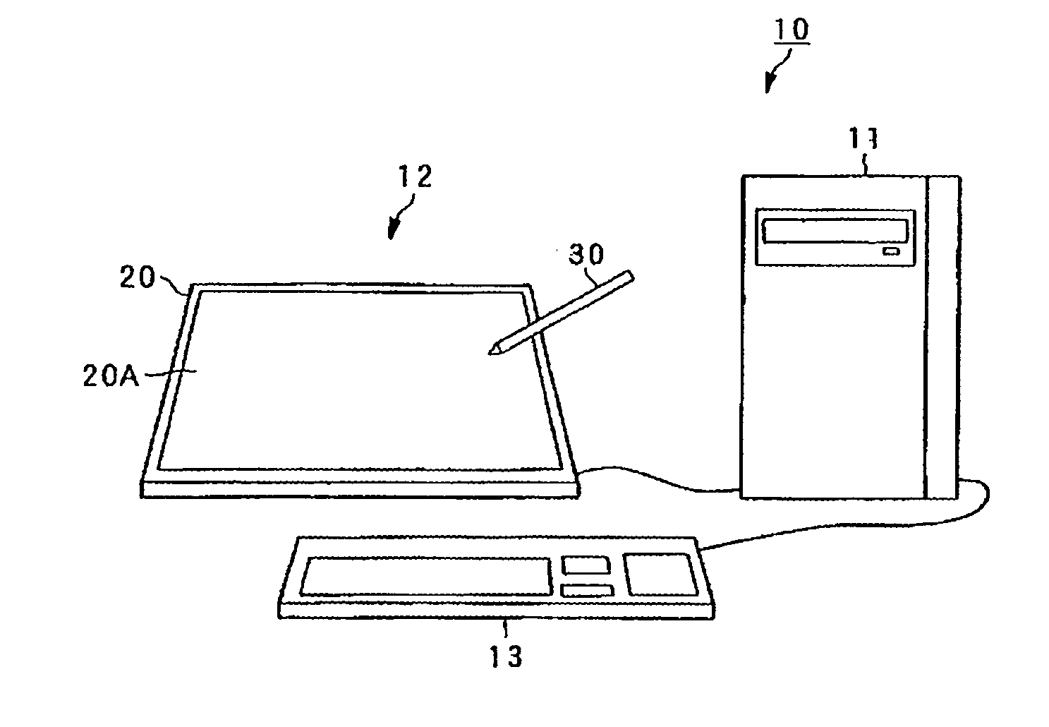
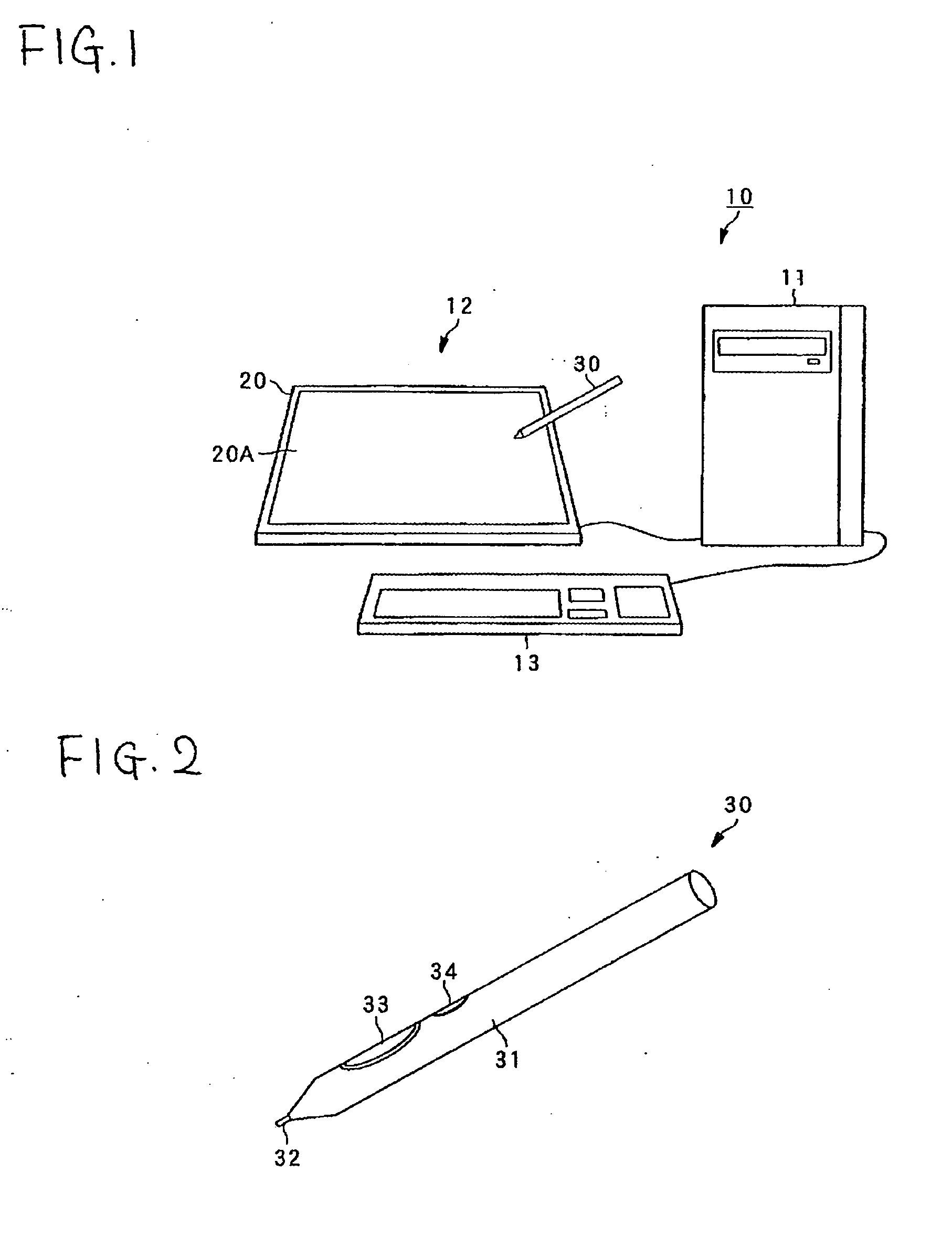
[0087]FIG. 1 shows an overview of a computer system 10 of a first embodiment of the invention.

[0088] In computer system 10 shown in FIG. 1, a monitor 12 and a keyboard 13 are connected to a computer main unit 11. An LCD (Liquid Crystal Display) or other display screen is integrated with a tablet 20 into the monitor 12 to perform position input using a position indicator 30, such as a pen. In addition, a charger 50, as best shown in FIG. 6A as a stand or holder, to charge the position indicator 30, described below, is connected to the computer main unit 11.

[0089] The tablet 20 (position detector device) functions as part of a position input system through use in conjunction with the position indicator 30, and detects a position indicated by the position indicator 30 on an input area 20A of the screen of the monitor 12, and outputs information, e.g., the position coordinates to the computer main unit 11.

[0090] The charger 50 is used to charge the position indicator 30, and is suppl...

modified example 1

[0135]FIG. 11 is a flowchart showing charging control processing in a modified example of the above first embodiment. The configuration of this modified example is similar to that of the computer system 10 of the above first embodiment, except for the operation of charging control processing.

[0136] In the charging control processing shown in FIG. 11, the CPU 101 of the computer main unit 11 counts the time elapsed from the previous charging of the position indicator 30 (step S11), and when this elapsed time has reached a prescribed time (step S11: Yes), a charging request message is displayed on the monitor 12 (step S12), and causes the supply of power from the interface portion 107 to the charger 50 to be started (step S13). Then, after a prescribed time has elapsed, the CPU 101 stops the supply of power to the charger 50 (step S14), returns to step S11, and counts the elapsed time.

[0137] In this case, even when the tablet 20 has not received charging request data from the positi...

modified example 2

[0138]FIG. 12 is a flowchart showing charging control processing in another modified example of the above first embodiment. The configuration of this modified example is similar to that of the system 10 of the above-described first embodiment, except for the operation of charging control processing.

[0139] In the charging control processing shown in FIG. 12, the CPU 101 of the computer main unit 11 counts the time elapsed from the previous charging of the position indicator 30 (step S21). When this elapsed time has reached a prescribed time (step S21: Yes), the CPU 101 determines whether the tablet 20 is able to receive signals transmitted from the position indicator 30 (step S22).

[0140] When no signals transmitted from the position indicator 30 are being received by the tablet 20 (step S22: No), the controller 401 displays a charging request message on the monitor 12 (step S23) and starts the supply of power from the interface portion 107 to the charger 50 (step S24). After a pres...


PUM


Abstract

A position input device is provided in which signals are transmitted from a position indicator, and signals transmitted from the position indicator are received by a position detector device. According to certain embodiments, an electrical double-layer capacitor, a charging circuit which charges the electrical double-layer capacitor, and a power transmission unit which relays and supplies to the charging circuit power supplied from a power supply unit external to the position indicator, are provided in the position indicator. In other embodiments the position input device has a built-in power supply unit, transmitting units, and a control unit for switching the transmitting units between energized and de-energized states. Also provided are position input systems and computer systems including the position input device, and methods of operating the position input device and the systems.

Description

CROSS-REFERENCES TO RELATED APPLICATIONS AND CLAIM TO PRIORITY [0001] The present application claims the benefit of Japanese Application No. P2005-357965, filed on Dec. 12, 2005, which application is incorporated herein by reference and to which priority is claimed. [0002] The present application also claims the benefit of Japanese Application No. P2006-073102 filed on Mar. 16, 2006, which application is incorporated hereby by reference and to which priority is claimed. FIELD OF THE INVENTION [0003] Aspects of this invention relate to a battery-free position pointing device (also referred to herein as a position indicator), a position input system, and a computer system which detect position by transmitting and receiving signals between the position indicator and the position detection device, and to related methods. [0004] Additional aspects of the present invention relate to a position pointing device with a built-in power source, a position input system, and a computer system sui...

Claims


Application Information

Patent Timeline
Patent Type & Authority Applications(United States)
IPC IPC(8): G06F3/033G06F3/041
CPCG06F3/03545G06F3/0416G06F3/04886G06F3/04162G06F3/04166G06F3/0442
Inventor KATSURAHIRA, YUJIMATSUBARA, MASAKI
Owner WACOM CO LTD
Why Eureka
Try Eureka