Liquid crystal display device and method of driving the same

a technology of liquid crystal display and display device, which is applied in non-linear optics, instruments, optics, etc., can solve the problem that the viewing angle cannot be narrow or wide, and cannot be adjusted to be narrow or wid

Active Publication Date: 2007-06-28
LG DISPLAY CO LTD
View PDF10 Cites 15 Cited by
  • Summary
  • Abstract
  • Description
  • Claims
  • Application Information

AI Technical Summary

Benefits of technology

[0013] An advantage of the present invention is to provide a liquid crystal display device having a viewing angle controlling function of changing a viewing angle to be wide when information is displayed on a display and to be narrow when the information is of a personal nature or security in a liquid crystal display device with a wide viewing angle, and a method of driving the same.
[0014] To achieve this and other advantages and in accordance with the purpose of the invention, as embodied and broadly described herein, a liquid crystal display device includes a first electrode and a second electrode on a first substrate, wherein a horizontal electric field is generated between the first and second electrodes, and a third electrode on a second substrate facing the first substrate, wherein a longitudinal electric field is generated between the third electrode and the first and second electrodes.
[0015] In another aspect of the present invention, a method of driving a liquid crystal display device includes forming a first electrode and a second electrode on a first substrate to generate a first electric field; forming a third electrode on a second substrate to generate a second electric field; and adjusting a voltage applied to the third electrode to control a viewing angle.

Problems solved by technology

However, according to the related art, even though the characteristics related to the viewing angle are improved, there is a limit that the viewing angle cannot be adjusted to be narrow or wide in order to maintain the security of displayed information.

Method used


Image

  • Liquid crystal display device and method of driving the same
  • Liquid crystal display device and method of driving the same
  • Liquid crystal display device and method of driving the same

Examples


Embodiment Construction

[0032] Reference will now be made in detail to the embodiments of the present invention, examples of which are illustrated in the accompanying drawings.

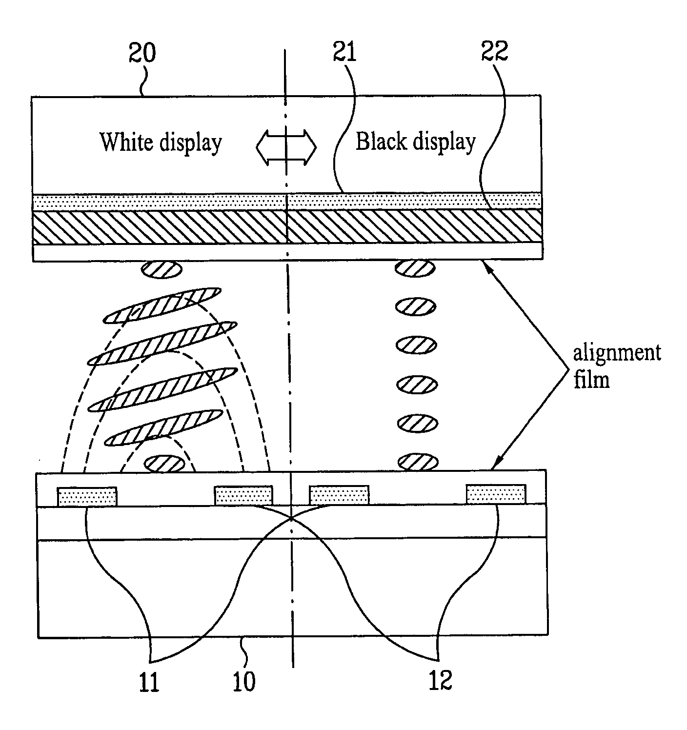
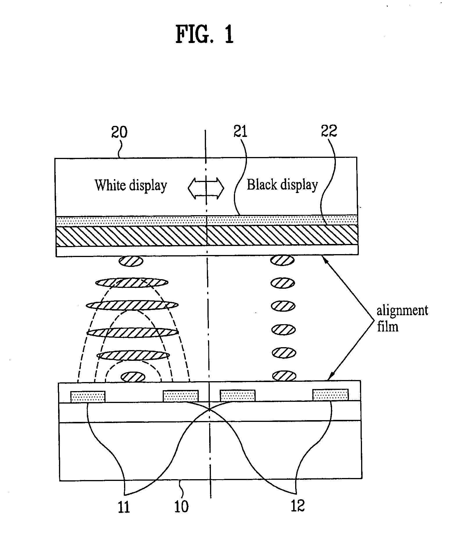
[0033]FIG. 1 is a schematic view illustrating a wide viewing angle mode in a liquid crystal display device having an in-plane switching (IPS) structure according to an embodiment of the present invention.

[0034] As illustrated in FIG. 1, a first electrode 11 and a second electrode 12 are formed on a substrate 10. A substrate 20 facing the substrate 10 has a third electrode 21.

[0035] A voltage of the third electrode 21 may be adjusted to decrease a longitudinal electric field so that a wide viewing angle mode is set.

[0036] The adjustment of the voltage applied to the third electrode 21 enables the switching between the wide viewing angle mode and a narrow viewing angle mode.

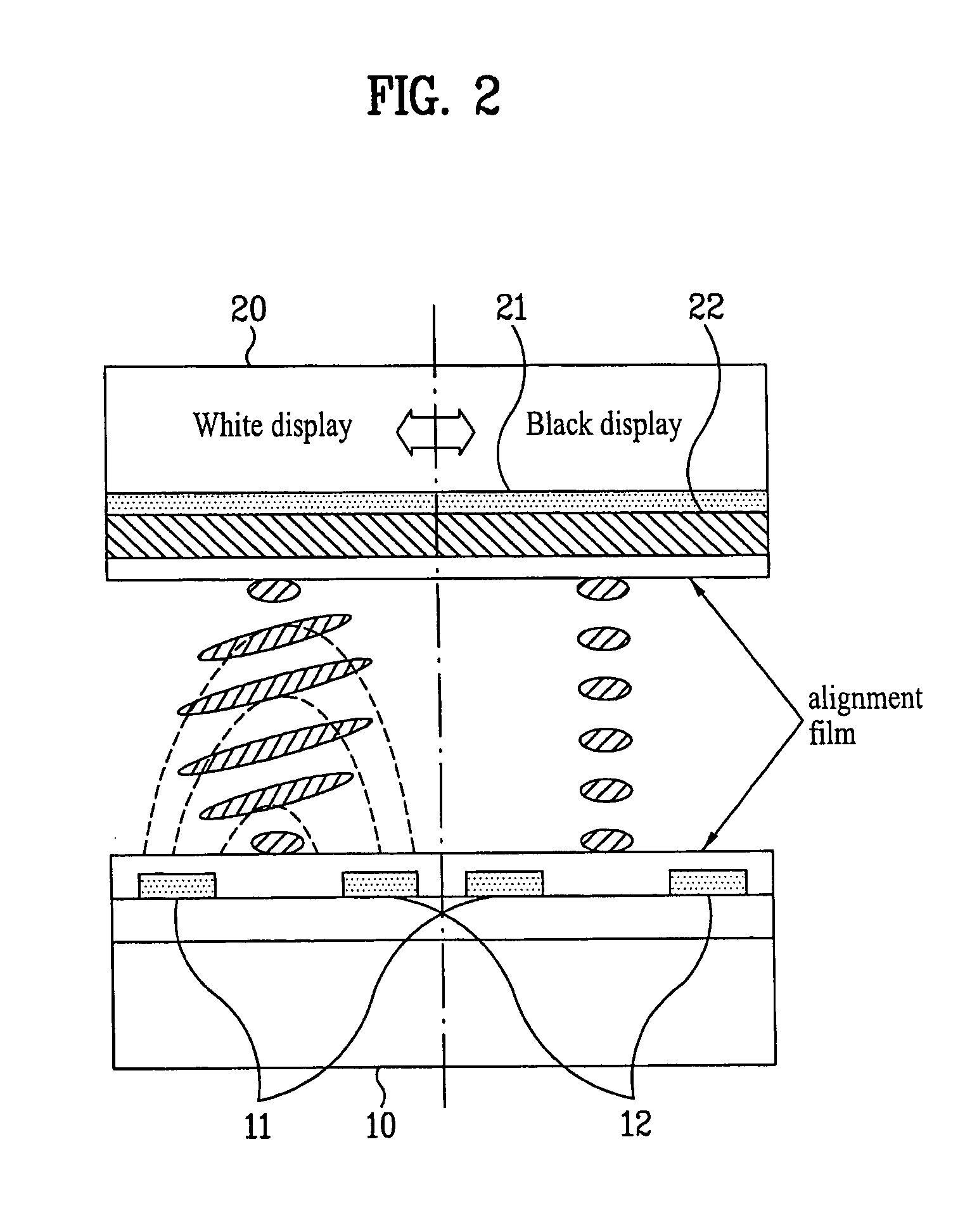
[0037]FIG. 2 is a schematic view illustrating a narrow viewing angle mode in a liquid crystal display device having an IPS structure according to an embodiment...


PUM

PropertyMeasurementUnit
viewing angleaaaaaaaaaa
rubbing angleaaaaaaaaaa
widthaaaaaaaaaa

Abstract

A liquid crystal display device includes a first electrode and a second electrode on a first substrate, wherein a horizontal electric field is generated between the first and second electrodes, and a third electrode on a second substrate, wherein a longitudinal electric field is generated between the third electrode and the first and second electrodes. In the liquid crystal display device, control of a wide viewing angle and a narrow viewing angle is enabled.

Description

[0001] This application claims the benefit of Japanese Patent Application No. JP 2005-379810 and JP2005-379830, filed on, Dec. 28, 2005, which are hereby incorporated by reference as if fully set forth herein. BACKGROUND OF THE INVENTION [0002] 1. Field of the Invention [0003] The present invention relates to a liquid crystal display device in which a wide viewing angle is controlled by controlling a longitudinal electric field, and a method of driving the same. [0004] 2. Discussion of the Related Art [0005] A liquid crystal display device, particularly, a liquid crystal display device using a thin film transistor (TFT) is widely used, for example, in a mobile communication telephone and a TV. [0006] Among the above-mentioned displays, there is required a personal display in which displayed content can be seen by a user of the personal display, but is not seen to another person who views the personal display in the horizontal direction. [0007] Particularly, the displayed content may...

Claims


Application Information

Patent Timeline
Patent Type & Authority Applications(United States)
IPC IPC(8): G02F1/1343
CPCG02F1/134363G02F2001/134381G02F1/134381
Inventor YAMASHITA, HIDEFUMI
Owner LG DISPLAY CO LTD
Why Eureka
Try Eureka