Advanced polarization imaging method, apparatus, and computer program product for retinal imaging, liquid crystal testing, active remote sensing, and other applications

a polarization imaging and imaging method technology, applied in the field of advanced polarization imaging methods, apparatuses and computer program products for retinal imaging, liquid crystal testing, active remote sensing, etc., can solve the problems of poor image quality, poor contrast mechanism, and inability to detect changes easily, so as to improve classification and identification of defects

Inactive Publication Date: 2007-06-28
THE ARIZONA BOARD OF REGENTS ON BEHALF OF THE UNIV OF ARIZONA
View PDF7 Cites 58 Cited by
  • Summary
  • Abstract
  • Description
  • Claims
  • Application Information

AI Technical Summary

Benefits of technology

[0049] Other embodiments address optical testing of optical systems. Considerable information on the order in liquid crystals, particularly for displays such as computer monitors, projectors, and LCoS TVs is obtained through the application of the invention. Other optical testing embodiments include the identification of bubbles and defects in optical materials and their identification and quantification, assessments of surface roughness, subsurface cracks and other surface defects in optical s

Problems solved by technology

The eye is subject to a number of pathologies and disease states which, if unchecked, lead to the impairment and possible loss of vision.
But the common eye diseases, including glaucoma, diabetic retinopathy, and Age-related Macular Degeneration (AMD) do not produce easily detectable changes during their early stages because many ocular structures are transparent and because others are obscured by opaque tissues.
Thus there are not that many strong contrast mechanisms for imaging to exploit.
But fundus imaging cannot detect AMD, early stage glaucoma, or the precursors to diabetic retinopathy.
Being interferometric, OCT images are speckle patterns making quantitative image analysis of small features very difficult.
OCT does not measure the polarization of transparent birefringent structures or depolarization and thus misses much useful information on the retina.
Several obstacles exist to determining retinal polarization by direct measurement.
Thus, the GDx device does not provide a full set of depolarization images of the retina and, therefore, does not provide a complete set of information about the deeper layers of the retina, lesions associated with neovascularization and basal and basal laminar deposits.
The Depolarization Index” is in widespread use to characterize the “strength” or “magnitude” of the depolarization but we will see that this metric can produce misleading results.
Therefore the Depolariz

Method used


Image

  • Advanced polarization imaging method, apparatus, and computer program product for retinal imaging, liquid crystal testing, active remote sensing, and other applications
  • Advanced polarization imaging method, apparatus, and computer program product for retinal imaging, liquid crystal testing, active remote sensing, and other applications
  • Advanced polarization imaging method, apparatus, and computer program product for retinal imaging, liquid crystal testing, active remote sensing, and other applications

Examples


Embodiment Construction

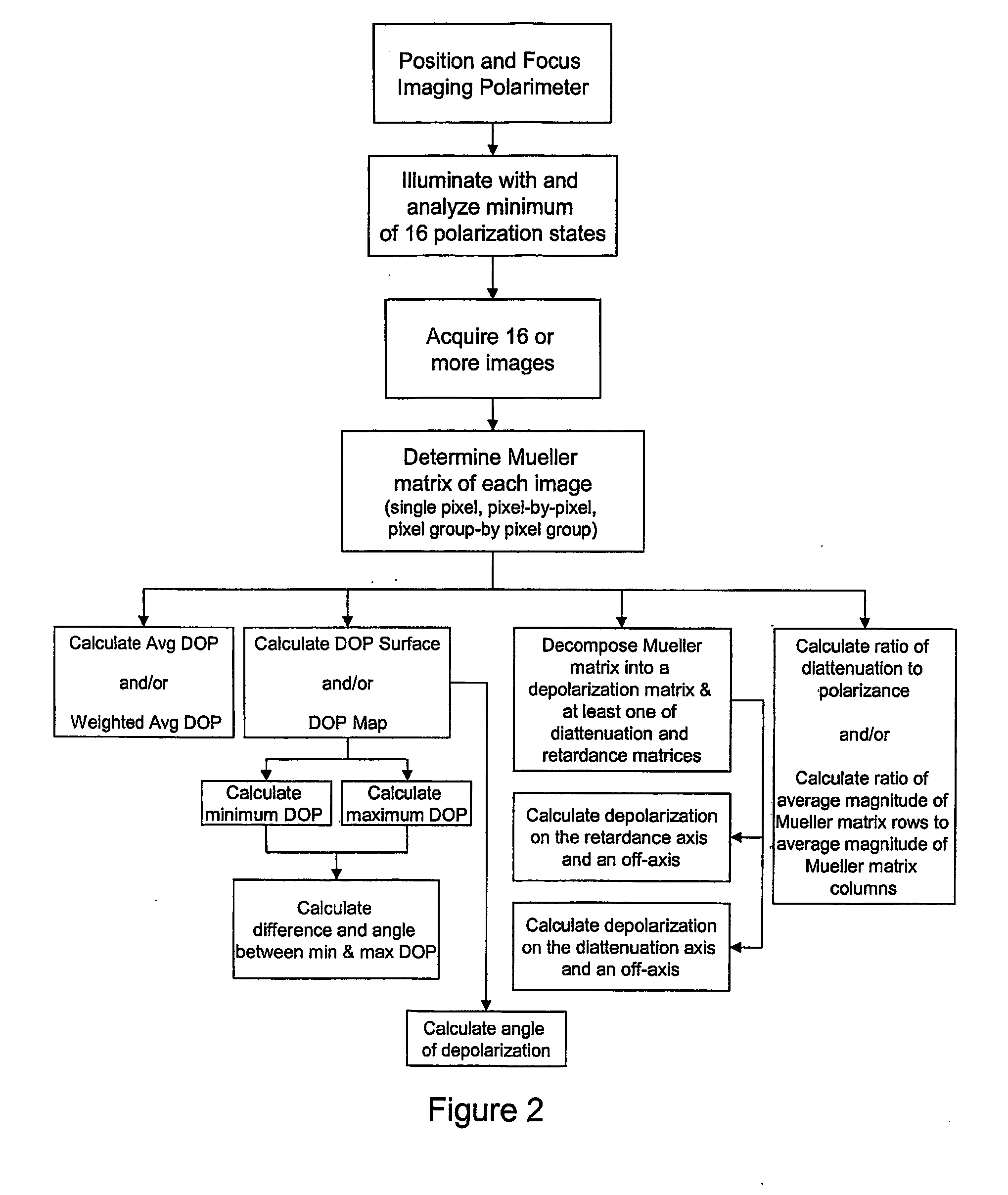
[0060] One cannot determine from a simple examination of a Mueller matrix how much depolarization the corresponding light / matter interaction causes because the change in the degree of polarization is a function of the incident polarization state. For most depolarizing light / matter interaction, some incident polarization states are depolarized more, and other states less. The invention provides new and useful ways of analyzing the variations of depolarization will reveal important characteristics of a sample.

[0061] Conventional systems and techniques are characterized by deficiencies of the Depolarization Index relative to describing the magnitude of depolarization. Here, a new depolarization metric is introduced as a single number which varies from zero to one to summarize the magnitude of depolarization of the light exiting a sample. This new metric is the Average Degree of Polarization or AverageDoP. The Average Degree of Polarization is calculated by integrating the DoP as the i...


PUM


Abstract

A method, apparatus, and computer program product for identifying features in a sample by analyzing Mueller matrices to calculate an average degree of polarization, a weighted average degree of polarization, a degree of polarization map, a degree of polarization surface. Also, a method, apparatus, and computer program product for identifying features in a sample by analyzing Mueller matrices to calculate depolarization relative to a retardance axis and/or a diattentuation axis, and to calculate a ratio of diattenuation to polarizance or ratios of row and column magnitudes. Also, a method for retinal polarimetry, including a non-depolarizing light tube configured for insertion into the eye.

Description

CROSS REFERENCE TO RELATED PATENT DOCUMENTS [0001] This application contains subject matter related to that disclosed in the following co-pending provisional patent application, the contents of which are incorporated herein by reference: U.S. Patent Application Ser. No. 60 / 492,805 filed on Aug. 6, 2003.BACKGROUND OF THE INVENTION [0002] 1. Field of Invention [0003] The invention describes a method utilizing actively illuminated imaging polarimetry for identifying a feature or features in an object through evaluation of how the object scrambles different incident fully polarized states into partially polarized states. Such a reduction in the degree of polarization of the light can be due to variations in the object below the resolution imaging system. [0004] 2. Description of the Background Art [0005] An active polarization image of an object, usually in the form of a Mueller matrix image, contains pixel-by-pixel information on the intensity, the retardance, and the diattenuation (pa...

Claims


Application Information

Patent Timeline
IPC IPC(8): A61B3/10G01J4/00G06T
CPCA61B3/12A61B3/1225G01J4/04G01N21/21G01N2021/217A61B3/14
Inventor CHIPMAN, RUSSELL
Owner THE ARIZONA BOARD OF REGENTS ON BEHALF OF THE UNIV OF ARIZONA
Why Eureka
Try Eureka