Planar light source device and display device using the same device
a technology of light source device and display device, which is applied in the direction of lighting support device, lighting and heating apparatus, instruments, etc., can solve the problems of lowering display quality, generating luminance and chromaticity unevenness, and lowering display quality
- Summary
- Abstract
- Description
- Claims
- Application Information
AI Technical Summary
Benefits of technology
Problems solved by technology
Method used
Image
Examples
embodiment 1
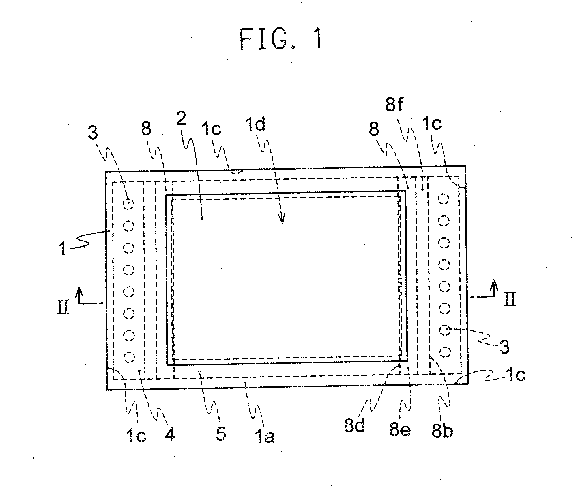
[0066]FIG. 1 is a plan view showing the schematic composition of a planar light source device related to Embodiment 1 of the present invention.
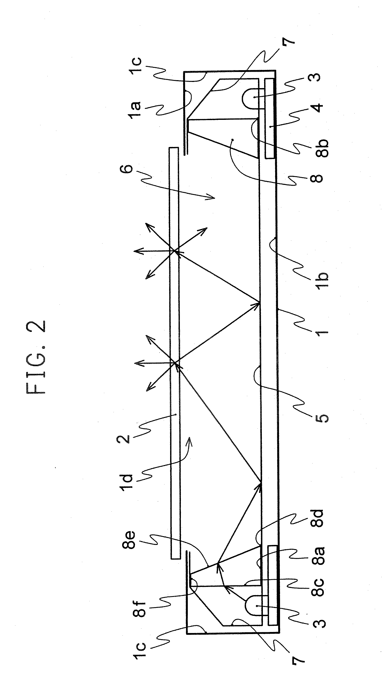
[0067]FIG. 2 is a partial section view of the II-II line of the planar light source device shown in FIG. 1. FIG. 3 is an LED arrangement chart showing one example of the arrangement of point light sources 3 using light emitting diodes (LEDs) and the like. FIG. 4 is a magnified view of a substantial part for illustrating the light path of light passing the refractive element. FIG. 5 is a view showing the light distribution of radiating light from LEDs which are used for the point light sources 3 related to Embodiment 1 of the present invention. In FIGS. 1 to 5, the housing 1 of the planar light source device is composed of a top face 1a, a bottom face 1b and 4 side planes 1c and has an opening portion 1d on the top face 1a.
[0068] The whole opening portion 1d of the housing 1 is provided with a scattering plate 2. The scattering plate 2 is a ...
embodiment 2
[0142]FIG. 26 is a partial section view of the planar light source device related to Embodiment 2 of the present invention. FIGS. 27(a) to 27(c) are partial section views of other refractive element related to Embodiment 2. In FIG. 26, the same numerals as FIGS. 1 to 25 show the same portions or equivalent portions, and their illustration is abbreviated. The refractive element 11 has the bottom face 11a which is nearly parallel to the bottom face 1b of the housing 1 or the scattering plate 2, the irradiated plane 11c which forms a fixed oblique angle θi at the reverse side from the first crista 11b to the bottom face 1b side of the housing 1 against the parallel bottom face 11a which passes the first crista 11b of the bottom face 11a in the point light sources 3 side, a plurality of faces 11g which are nearly parallel to the bottom face 11a, the radiating planes 11e which form a fixed oblique angle θ2 at the reverse side from the cristas 11d to the bottom face 1b side of the housing...
embodiment 3
[0150]FIG. 28 is a partial section view of the planar light source device related to Embodiment 3 of the present invention. FIGS. 29(a) and 29(b) are evolution charts showing the refractive element related to Embodiment 3, FIG. 29(a) is a top view viewed from the top face side of the housing, and FIG. 29(b) is a frontal view viewed from the hollow space side. FIG. 30 is an illustration view showing a light path possibly occurring when light transmitting in the refractive element is totally reflected on a radiating plane. In FIGS. 28 to 30, the same numerals as FIGS. 1 to 27(c) show the same portions or equivalent portions, and their illustration is abbreviated.
[0151] The refractive element 12 has the bottom face 12a which is nearly parallel to the bottom face 1b of the housing 1 or the scattering plate 2, the irradiated plane 12c which forms a fixed oblique angle θ1 at the reverse side from the first crista 12b to the bottom face 1b side of the housing 1 against the bottom face 12a...
PUM
 Abstract
Description
Claims
Application Information
 - R&D
- Intellectual Property
- Life Sciences
- Materials
- Tech Scout
- Unparalleled Data Quality
- Higher Quality Content
- 60% Fewer Hallucinations
Browse by: Latest US Patents, China's latest patents, Technical Efficacy Thesaurus, Application Domain, Technology Topic, Popular Technical Reports.
© 2025 PatSnap. All rights reserved.Legal|Privacy policy|Modern Slavery Act Transparency Statement|Sitemap|About US| Contact US: help@patsnap.com


