
Auto adaptive quality of service architecture and associated method of provisioning customer premises traffic

a service architecture and quality technology, applied in the field of telecommunication architecture, can solve the problems of customer premises equipment, network edge, inability to benefit from such network management schemes and qos technologies, and complicating the adoption of this technology

Inactive Publication Date: 2007-06-28
FRANCE TELECOM SA
View PDF12 Cites 148 Cited by
  • Summary
  • Abstract
  • Description
  • Claims
  • Application Information

AI Technical Summary

Benefits of technology

[0015]FIG. 3 is a high level block diagram of a guardian control module of the gateway device of FIG. 2;
[0016]FIG. 4 is a flowchart describing an exemplary traffic shaping operation

Problems solved by technology

While these techniques are highly effective, customer premises equipment, which by its nature is external to the network edge, cannot benefit from such network management schemes and QOS technologies.
However, competing protocols and methodology are complicating the adoption of this technology.
Further, the adoption of such an increasingly complex layering of control and routing protocols is not a cost effective solution for residential and / or most smaller to medium sized enterprise customers.
This basic interface provided by the service provider does not provide any QOS funtionality, nor can it shape traffic exchanged therethrough in an upstream or downstream direction.
Consequently, many residential customers, get very bad quality of service due to bandwidth limitations in the last mile.
For example, current residential services, whether offered over DSL, cable modem ,or by Wireless Service Provider (WISP), do not guarantee QoS to the customer.
Likewise, there is no way by which a priority can be assigned to data streams in the last mile such that one data stream, or “active session,” can be given priority with respect to available last mile resources.

Method used


Image

  • Auto adaptive quality of service architecture and associated method of provisioning customer premises traffic
  • Auto adaptive quality of service architecture and associated method of provisioning customer premises traffic
  • Auto adaptive quality of service architecture and associated method of provisioning customer premises traffic

Examples


Embodiment Construction

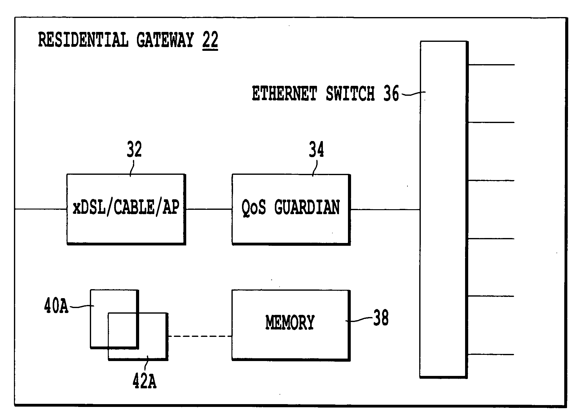
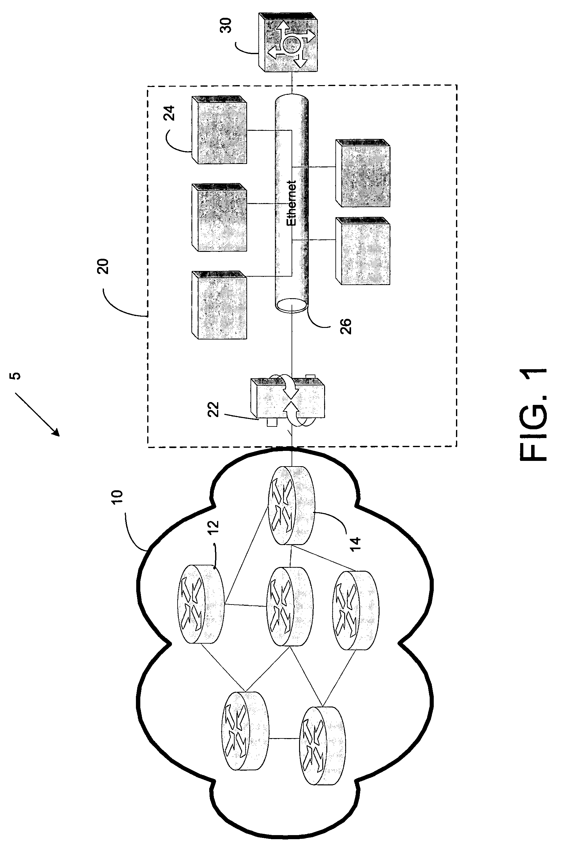
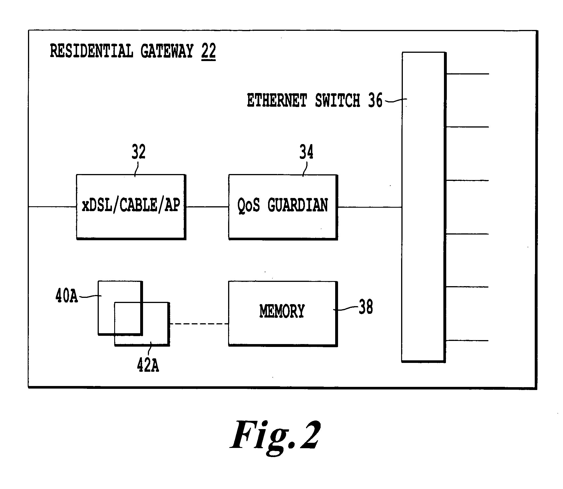
[0018] Certain terminology used in the following description is for convenience only and is not limiting. The term “gateway” as used herein refers to hardware and / or software functioning to interface between a customer / enterprise and a provider edge. No functionality is either implied or inferred from the use of the term “gateway” aside from that described herein. Likewise, “customer premises” is not limited with respect to physical location, but, instead, merely denotes functionality with respect to the exchange of traffic with a customer. As such, the customer premises device (CPE) may be physically located at any distance from home network or enterprise network point of presence. The ability to pass communications therebetween being a function of the transmission range, power and wireless / hardwire application protocol of the respective devices. In the drawings, the same reference numerals are used for designating the same elements throughout the several figures.

[0019] The presen...


PUM


Abstract

A customer premises device is provided for monitoring quality of service (QOS) metrics between a network edge and a customer. The device includes a memory which stores at least one user profile, and, information regarding active sessions of traffic flow through the customer premises device. A hardware and / or software / firmware based controller monitors traffic flow between the customer and the network edge and receives requests for new active sessions. The processor accesses the at least one user profile stored in memory to identify a policy hierarchy with respect to active sessions of traffic flow upon receipt of a request to establish a new active session. The processor selects a candidate active session to be terminated based upon the policy hierarchy and terminates the selected session in accordance with information stored in memory regarding the selected session. In this manner, the processor enforces quality of service, for both upstream and downstream sessions, based upon the policy hierarchy of the user profile.

Description

BACKGROUND OF THE INVENTION [0001] The present invention relates to a telecommunication architecture and associated method of extending quality of service (QOS) control beyond the network edge, and, more specifically, to an auto adaptive full duplex QOS mechanism for customer premises equipment (CPE), such as a residential / enterprise gateway. [0002] The “background” description provided herein is for the purpose of generally presenting the context of the invention. Work of the presently named inventors, to the extent it is described in this background section, as well as aspects of the description which may not otherwise qualify as prior art at the time of filing, are neither expressly or impliedly admitted as prior art against the present invention. [0003] Currently, QOS is primarily controlled internal to the network edge (i.e., network core or “backbone”) via a multitude of routing and resource allocation mechanisms. In a typical Wide Area Network (WAN) environment, the Internet ...

Claims


Application Information

Patent Timeline
IPC IPC(8): H04J1/16
CPCH04L12/5695H04L47/15H04L47/20H04L47/22H04L47/2425H04L47/745H04L47/765H04L47/788H04L47/808H04L47/70
Inventor KALONJI, NDIATAMOURYA, MANOJ
Owner FRANCE TELECOM SA
Learn More