
Obtaining multiple port addresses by a fibre channel switch from a network fabric

a fibre channel switch and network fabric technology, applied in the field of data communication, can solve the problems of switching being unable to establish a link, no direct connection method, and lack of interoperability between dissimilar fc switches

Inactive Publication Date: 2007-06-28
IBM CORP
View PDF5 Cites 39 Cited by
  • Summary
  • Abstract
  • Description
  • Claims
  • Application Information

AI Technical Summary

Benefits of technology

[0014] The accompanying drawings, which are incorporated in and constitute part of this specification, illustrate embodiments of the invention and together with the description, serve to explain the principle

Problems solved by technology

There is no method for directly connecting switches that do not share a common ISL protocol.
These vendor-provided extensions cause these switches to be unable to establish a link with switches that do not support the same set of extensions.
This lack of interoperability between dissimilar FC switches is a major impediment to deploying new FC technology into existing SANs.
An alteration of an E_Port link will disrupt the SAN fabric management structure, and consequently can cause a momentary disruption across the entire SAN, while the interconnected switches re-establish the management hierarchy and restore the switch to switch communications.
Another problem associated with inter-switch links is management security risk.
The Inter-switch links extend the SAN, as well as the risk of unwanted SAN management access, to every connected switch in the fabric.
Consequently, there is no way to aggregate server or device FC connections directly from one FC switch to another without extending the security risk as well.
However, changing to the FC-SW-2 mode (also known as open mode) is disruptive to the SAN, requires operational changes to the management of the SAN and disables features that can be selected and used in the vendor's private extensions.
Inserting a router between two switches introduces a performance characteristic that can lead to performance and scalability limitations.
The equipment necessary to perform this task remains expensive for the performance levels needed in a large SAN.

Method used


Image

  • Obtaining multiple port addresses by a fibre channel switch from a network fabric
  • Obtaining multiple port addresses by a fibre channel switch from a network fabric
  • Obtaining multiple port addresses by a fibre channel switch from a network fabric

Examples


Embodiment Construction

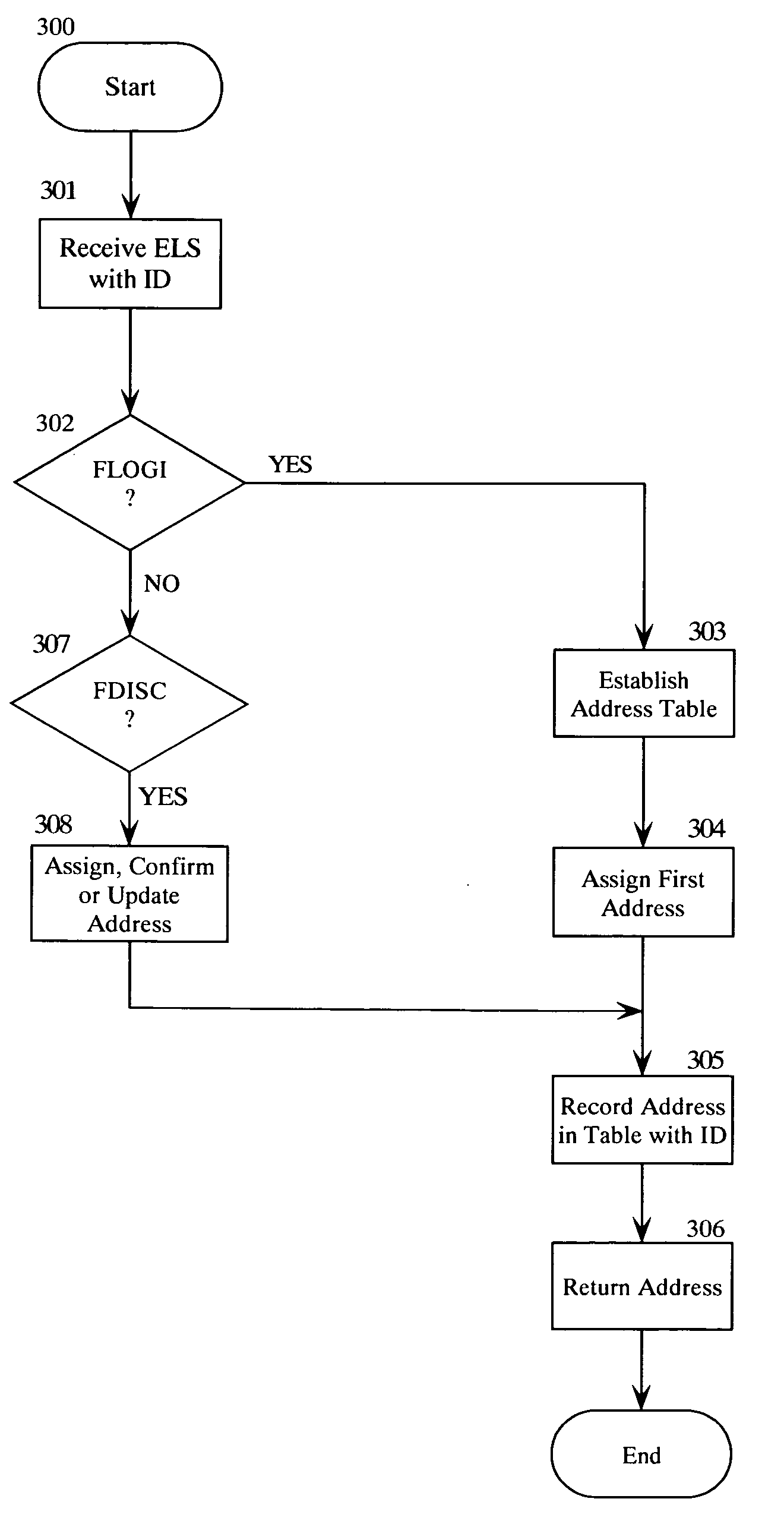
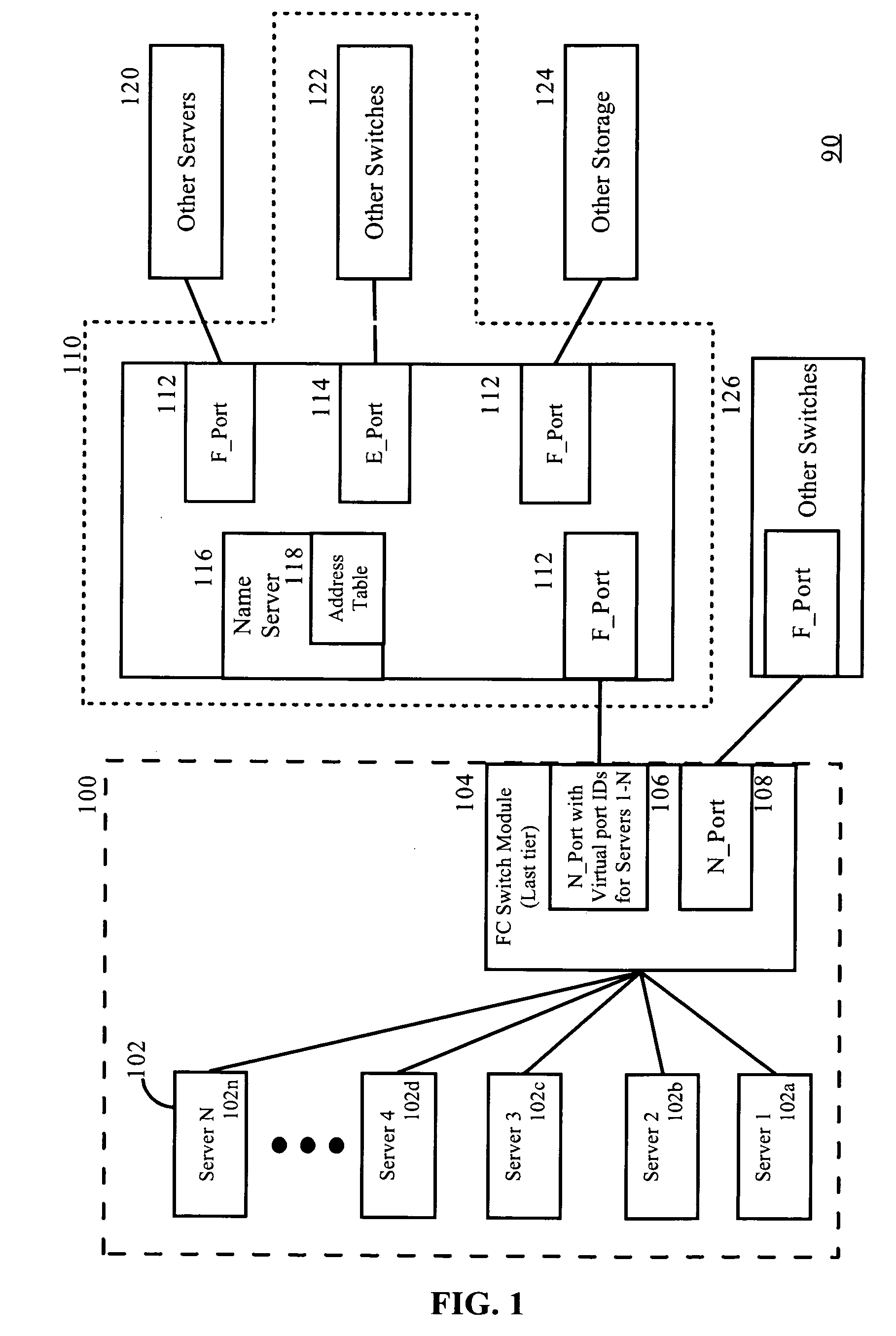
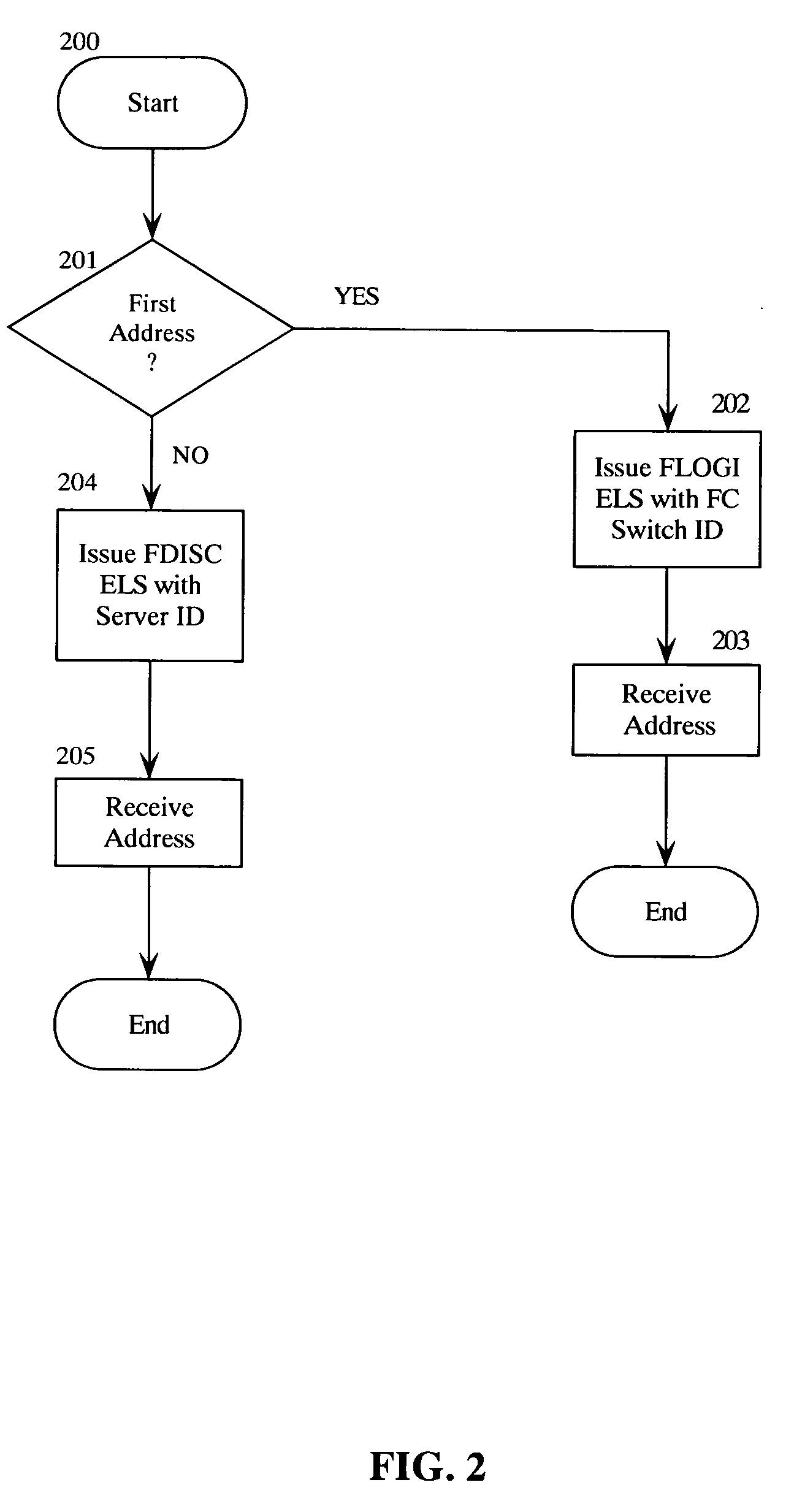
[0018] The present invention provides a data processing system, method and computer program product for obtaining multiple port addresses by a FC switch directly from a SAN fabric. The invention provides a FC Switch Module configured to provide an interface between multiple servers and a SAN fabric. The FC Switch Module provides “NPIV port” mode support and connects to the SAN fabric as an N_Port to establish port identification (N_Port IDs) for itself, if desired, and for each Host Bus Adaptor (HBA) port that connects to the FC Switch Module on behalf of a server.

[0019] The fabric can provide support for NPIV connected servers, as is know in the art. That support is sufficient for the fabric to support this new “NPIV port” mode from the FC Switch Module.

[0020] In illustration, FIG. 1 is a block diagram illustrating a data communications network configured with an FC Switch Module programmed to obtain multiple port identifications (N_Port ID) directly from a SAN fabric. As shown i...


PUM


Abstract

Embodiments of the present invention address deficiencies of the art in respect to Fibre Channel (FC) switch interoperability and provide a novel and non-obvious data processing system, method and computer program product for obtaining multiple port addresses by a FC switch directly from a SAN fabric. In one embodiment, the system uses an N_Port connection from the last tier FC SAN switch to connect to the rest of the SAN fabric and employs the N_Port ID Virtualization (NPIV) Fibre Channel feature. The NPIV feature allows one physical FC port (N_Port) to login to a SAN fabric multiple times and receive unique N_Port IDs with each login. This allows the one physical FC port (N_Port) to act as multiple logical N_Ports.

Description

BACKGROUND OF THE INVENTION [0001] 1. Field of the Invention [0002] The present invention relates to data communications and more particularly to a Fibre Channel (FC) switch. [0003] 2. Description of the Related Art [0004] Fibre Channel (FC) switches are used to connect servers to storage services and resources, for creating a storage area network (SAN). In computing, a storage area network (SAN) is a network designed to attach computer storage devices such as disk array controllers and tape libraries to servers. The SAN fabric is an active intelligent interconnection scheme that utilizes the Fibre Channel Architecture. Servers and storage devices connect to FC SAN switches as an N_Port (node port), while the switch provides an F_Port (fabric port). When two FC SAN switches are connected together to enlarge the switch fabric, they will utilize an unique port type, an E-Port on each end. E_Ports implement a unique mechanism to exchange configuration and topology information between t...

Claims


Application Information

Patent Timeline
IPC IPC(8): H04J1/16H04J3/22
CPCH04L67/1097H04L49/357H04L49/25
Inventor HOLLAND, WILLIAM
Owner IBM CORP
Learn More