Performance testing apparatus for heat pipes

a technology of performance testing and heat pipes, which is applied in the direction of lighting and heating apparatus, instruments, heat measurement, etc., can solve the problems of inability to precisely reflect the performance of the heat pipe, inability to obtain rth and qmax, and inability to achieve precise heat pipe performan

Inactive Publication Date: 2007-06-28
HON HAI PRECISION IND CO LTD
View PDF9 Cites 10 Cited by
  • Summary
  • Abstract
  • Description
  • Claims
  • Application Information

AI Technical Summary

Benefits of technology

[0010]A performance testing apparatus for a heat pipe in accordance with a preferred embodiment of the present invention comprises an immovable portion having a heating member located therein for heating an evaporating section of the heat pipe, and a movable portion capable of moving relative to the immovable portion. A receiving structure is defined between the immovable portion and the movable portion for receiving the evaporating section of the heat pipe therein. A positioning structure extend from at

Problems solved by technology

However, Rth and Qmax can not be obtained by this test, and the performance of the heat pipe can not be reflected exactly by this test.
However, in the test, the related testing apparatus has the following drawbacks: a) it is difficult to accurately determine lengths of the evaporating section 2a and the condensing section 2b which are important factors in determining the performance of the heat pipe 2; b) heat transference and temperature measurement may e

Method used


Image

  • Performance testing apparatus for heat pipes
  • Performance testing apparatus for heat pipes
  • Performance testing apparatus for heat pipes

Examples


Embodiment Construction

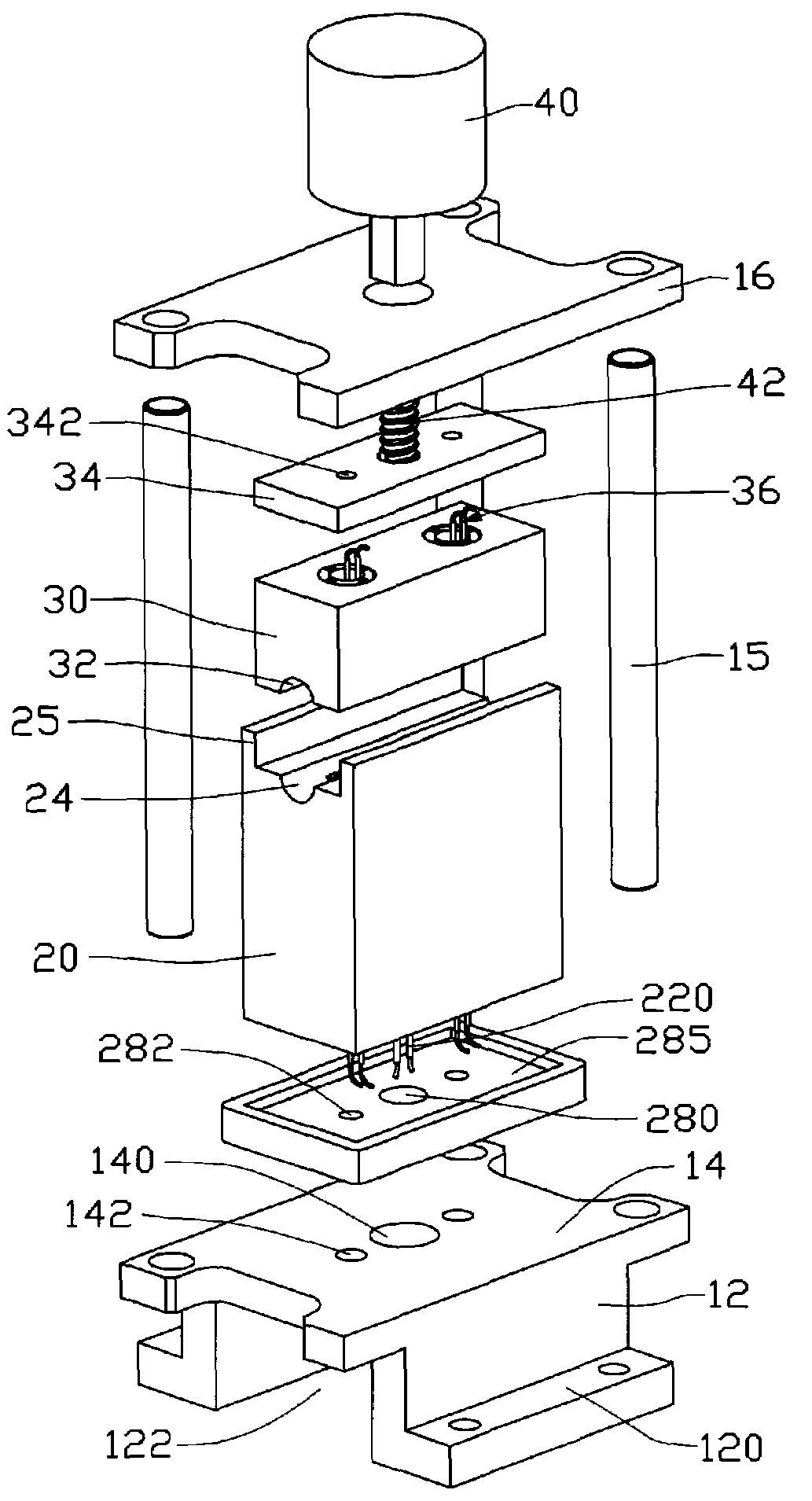
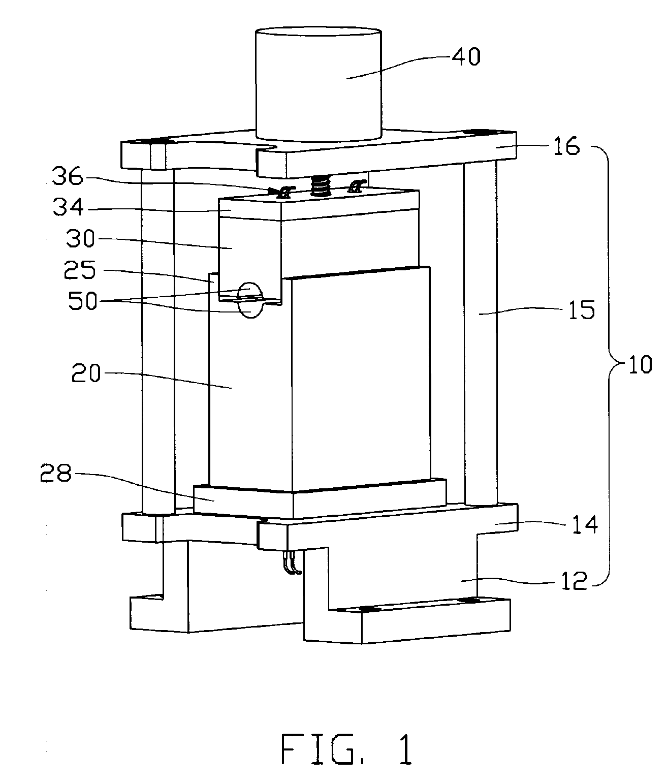
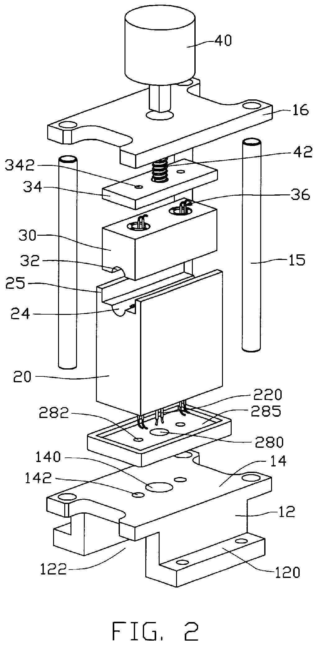
[0020]Referring to FIGS. 1 and 2, a performance testing apparatus for heat pipes in accordance with a preferred embodiment of the present invention comprises an immovable portion 20 and a movable portion 30 movably mounted on the immovable portion 20.

[0021]Referring also to FIGS. 3A and 3B, the immovable portion 20 has good heat conductivity and is held on a platform of a supporting member such as a testing table or so on. A heating member 22 such as an immersion heater, resistance coil, quartz tube and Positive temperature coefficient (PTC) material or the like is embedded in the immovable portion 20. The immovable portion 20 defines a hole (not shown) through a center of a bottom thereof. In the case, the heating member 22 is an elongated cylinder. The heating member 22 is accommodated in the hole (not shown) of the immovable portion 20 from the bottom of the immovable portion 20. Two spaced wires 220 extend from a bottom end of the heating member 22 to connect with a power supply...


PUM


Abstract

A performance testing apparatus for a heat pipe includes an immovable portion having a heating member located therein for heating an evaporating section of the heat pipe, and a movable portion capable of moving relative to the immovable portion. A receiving structure is defined between the immovable portion and the movable portion for receiving the evaporating section of the heat pipe therein. A positioning structure extends from the immovable portion and slideably receives the movable portion therein for avoiding the movable portion from deviating from the immovable portion during movement of the movable portion relative the immovable portion. Temperature sensors are attached to the immovable portion and the movable portion for detecting temperature of the heat pipe.

Description

FIELD OF THE INVENTION[0001]The present invention relates generally to testing apparatuses, and more particularly to a performance testing apparatus for heat pipes.DESCRIPTION OF RELATED ART[0002]It is well known that a heat pipe is generally a vacuum-sealed pipe. A porous wick structure is provided on an inner face of the pipe, and phase changeable working media employed to carry heat is included in the pipe. Generally, according to where the heat is input or output, a heat pipe has three sections, an evaporating section, a condensing section and an adiabatic section between the evaporating section and the condensing section.[0003]In use, the heat pipe transfers heat from one place to another place mainly by exchanging heat through phase change of the working media. Generally, the working media is a liquid such as alcohol or water and so on. When the working media in the evaporating section of the heat pipe is heated up, it evaporates, and a pressure difference is thus produced bet...

Claims


Application Information

Patent Timeline
IPC IPC(8): G01K1/14G01K13/00
CPCF28D15/0283F28F2200/005
Inventor LIU, TAY-JIANSUN, CHIH-HSIENTUNG, CHAO-NIENHOU, CHUEN-SHU
Owner HON HAI PRECISION IND CO LTD
Why Eureka
Try Eureka