Disposable needle and hub assembly

a hub assembly and injection needle technology, applied in the direction of intravenous devices, infusion needles, other medical devices, etc., can solve the problems of reducing the overall effective needle length, reducing the effective depth of injection, so as to facilitate stress concentration relocation, facilitate injection accuracy, protection and forgiveness

Active Publication Date: 2007-06-28
EMBECTA CORP
View PDF9 Cites 180 Cited by
  • Summary
  • Abstract
  • Description
  • Claims
  • Application Information

AI Technical Summary

Benefits of technology

[0015] The design of the needle hub assembly according to an embodiment of the present invention ergonomically suggests a proper insertion technique that is substantially perpendicular to the skin to fully seat the needle into skin, which facilitates delivering the injection accurately to the desired depth.
[0016] The center hub protrusion used in embodiments of the present invention provides protection and forgiveness from cannula buckling or fracture when misused or used in accordance with poor technique. In addition, the center hub protrusion used in embodiments of the present invention facilitates stress concentration relocation, thereby sharing cannula angular bending along an irregular surface and preventing a lateral stress of 90 degrees or more.
[0017] In yet other embodiments of the present invention, a deepened well also provides protection and forgiveness from cannula buckling or fracture when misused or used in accordance with poor technique. The needle protrusion from the deepened well used in embodiments of the present invention facilitates stress concentration relocation, thereby sharing cannula angular bending along an irregular surface and preventing a lateral stress of 90 degrees or more.
[0018] Another advantage of embodiments of the present invention is that during the removal of the needle after injection, the contact plane of the needle hub assembly provides a fulcrum action at the outer ring or shroud that allows only a finite amount of the cannula to bend before proactively reducing further damage by serving to pry or withdraw the cannula from the tissue.

Problems solved by technology

In order to achieve the desired injection depths for shallow subcutaneous and intradermal injections, conventional needle hub assemblies may have a depth-limiting attachment to achieve the desired injection depth, which requires the needle to be longer in length and less structurally resilient to non-perpendicular insertion caused by improper injection technique and general misuse overall.
The height of the adhesive bump 45 from one needle assembly to the next is not uniform, but the bumps generally fall within a predetermined maximum tolerance unsuitable for shallow drug delivery.
Even within this tolerance the bump reduces the overall effective needle length, to varying extents from needle-to-needle, which can significantly affect depth of medication delivery.
Other negative effects of the adhesive bump include potential bruising to the patient when administered an injection and producing a single lateral stress point at the needle / bump junction which can cause the needle cannula 31 to more easily bend when used improperly.
However, at times when a biological sharps disposal container is not available, a user may decide to wait until such a container is available.
Typically, if a container for disposal of sharp biological instruments is not available, users of the injection device improperly place the used needle hub assembly in a pocket or purse for proper disposal at a later time, which may result in inadvertent needle sticks during storage, transportation, or disposal of the needle hub.
The snap-fit 35 is difficult to manufacture and raises the overall manufacturing costs of the device.

Method used


Image

  • Disposable needle and hub assembly
  • Disposable needle and hub assembly
  • Disposable needle and hub assembly

Examples


Embodiment Construction

[0041] The following description and details of exemplary embodiments of the present invention, while generally disclosed in a typical pen needle hub configuration, could more broadly apply to a needle and hub assembly for use in conjunction with, or incorporated onto, other injection devices such as syringes and infusion devices. In the case of a disposable pen needle application, the user would generally handle embodiments of the invention in the same manner as a typical commercially available pen needle.

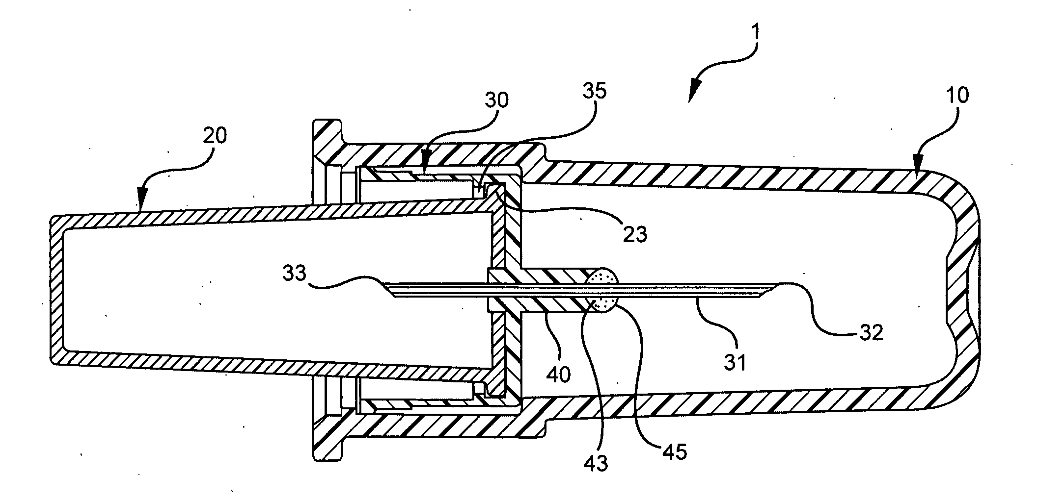
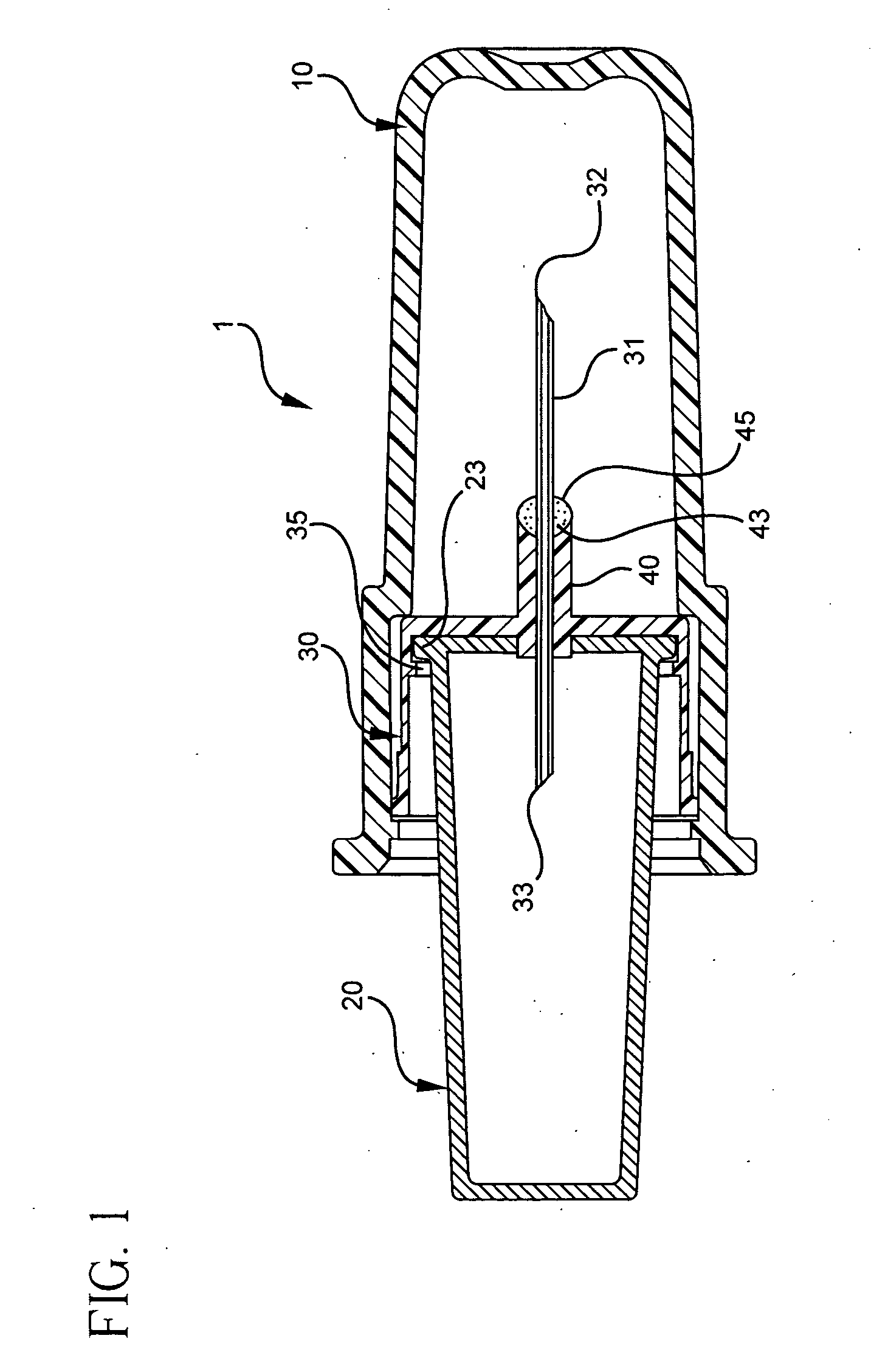
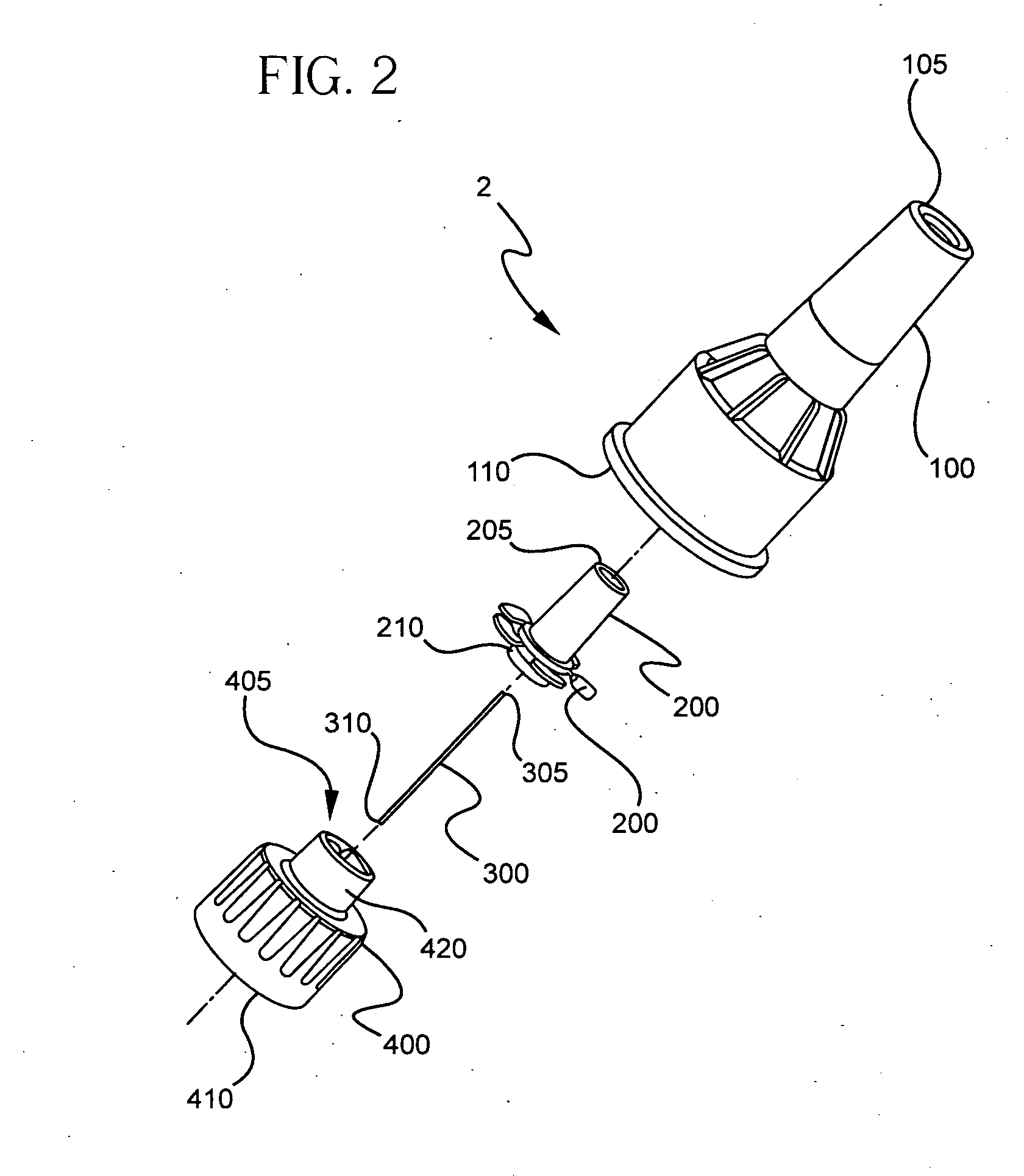
[0042] A pen needle assembly according to an embodiment of the present invention is shown in FIG. 2. The pen needle assembly 2 comprises a cover 100, an inner shield 200, a needle cannula 300, and a hub 400 The proximal end 310 of the needle cannula 300 is inserted into a center opening in the distal (patient) end 405 of the hub 400 until a predetermined length of the distal end 305 of the needle cannula 300 remains extended. The needle cannula 300 is secured by epoxy or adhesive...


PUM


Abstract

A needle assembly including a cover, an inner shield, a needle and a hub assembly is provided. After use, the cover is placed over the distal (patient) end of the needle and the inner shield can be used to cover the proximal (non-patient) end of the needle. The inner shield comprises flexible extensions above its open end to secure the inner shield over the proximal end of a needle in the needle assembly. A needle hub is also provided that eliminates adhesive bumps at the base of the needle and further distributes needle angular bending along an irregular surface, which facilitates proper insertion technique and effective needle length. The hub further includes stanchions or castellations on its edge such that when the patient uses proper injection techniques, the edges of the hub leave a distinctive impression in the skin of a user for a short period of time.

Description

[0001] This Application is claiming the benefit under 35 U.S.C. 119(e) to Provisional Application Ser. No. 60 / 60 / 725,637, filed Oct. 13, 2005.FIELD OF THE INVENTION [0002] The present invention relates generally to a disposable injection needle and hub assembly, particularly one in which the hub provides an effective usable needle length and a non-patient needle end shield. These features allow a user to administer medication into a tissue layer at a predetermined depth, and to dispose of the device without fear of injury due to the exposed needle tip. BACKGROUND OF THE INVENTION [0003] Insulin injections are traditionally given with either an insulin syringe, usually having an integrated needle permanently or semi-permanently incorporated, or an insulin pen whereby a disposable pen needle is attached to facilitate drug container access and allow fluid egress from the container through the needle into the patient. As technology and competition advance, driving the desire for shorter...

Claims


Application Information

Patent Timeline
Patent Type & Authority Applications(United States)
IPC IPC(8): A61M5/00
CPCA61M5/002A61M5/3205A61M5/3213A61M5/3286A61M5/3287A61M2205/583A61M5/3293A61M5/343A61M5/349A61M5/46A61M2005/341A61M5/329
Inventor MARSH, RONALD W.
Owner EMBECTA CORP
Why Eureka
Try Eureka