
Generating a Hardware Description from a Graphical Program in Response to Receiving a Diagram with States and State Transitions

a graphical program and state diagram technology, applied in the field of graphical programming, can solve the problem that the gpg program does not automatically generate a complete graphical program, and achieve the effect of facilitating the dynamic update of the graphical program

Inactive Publication Date: 2007-06-28
NATIONAL INSTRUMENTS
View PDF52 Cites 29 Cited by
  • Summary
  • Abstract
  • Description
  • Claims
  • Application Information

AI Technical Summary

Benefits of technology

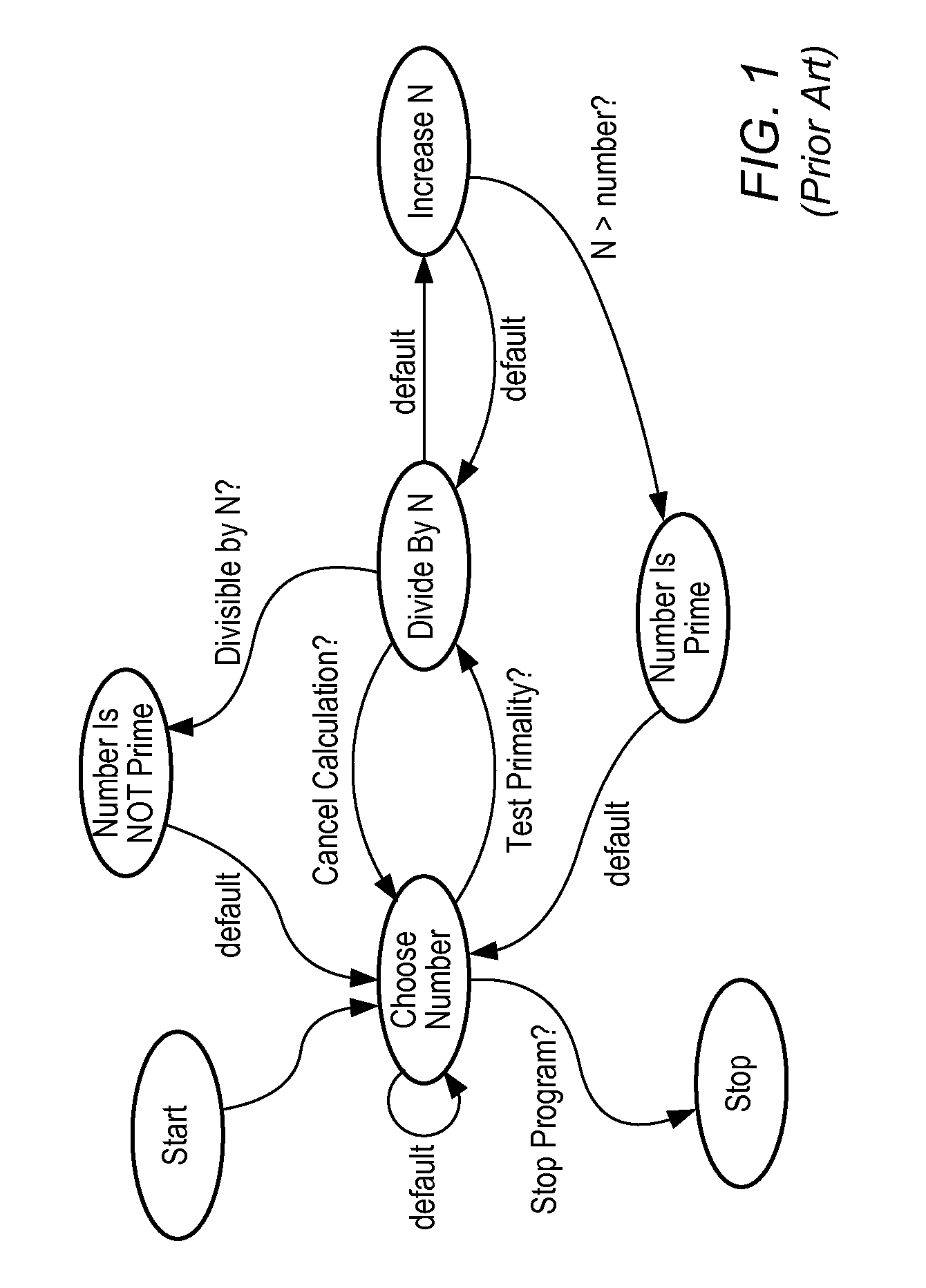
[0029] During execution of the graphical program, for each state, program instructions may be executed when that state is active. In one embodiment these instructions (and the functionality performed by these instructions) may not be specified by the state diagram information. Thus, the GPG program may not automatically generate a complete graphical program that implements the functionality that the state diagram is intended to represent. In this instance, the graphical source code framework automatically generated by the GPG program may be organized to correspond to the state diagram information and may include various “placeholders” or “containers” enabling the user to easily fill in the graphical program with source code that specifies execution instructions for each state and Boolean conditions for each state transition.
[0035] In one embodiment, the generated graphical program may be “locked”, requiring the user to explicitly unlock the graphical program before certain modifications to the graphical program can be made within the graphical programming environment. Locking the graphical program may ensure that the program's graphical source code is in a state known or expected by the GPG program, thus facilitating the dynamic update of the graphical program. For example, in one embodiment, the user may be allowed to add source code to the graphical program that specifies execution instructions for each state and Boolean conditions for each state transition, and may also be allowed to resize objects created by the GPG program, but may be prevented from modifying the topology of the framework programmatically generated by the graphical program until the graphical program is unlocked.

Problems solved by technology

Thus, the GPG program may not automatically generate a complete graphical program that implements the functionality that the state diagram is intended to represent.

Method used


Image

  • Generating a Hardware Description from a Graphical Program in Response to Receiving a Diagram with States and State Transitions
  • Generating a Hardware Description from a Graphical Program in Response to Receiving a Diagram with States and State Transitions
  • Generating a Hardware Description from a Graphical Program in Response to Receiving a Diagram with States and State Transitions

Examples


Embodiment Construction

Incorporation by Reference

[0053] The following references are hereby incorporated by reference in their entirety as though fully and completely set forth herein.

[0054] U.S. Pat. No. 5,481,741 titled “Method and Apparatus for Providing Attribute Nodes in a Graphical Data Flow Environment,” issued on Jan. 2, 1996.

[0055] U.S. patent application Ser. No. 09 / 745,023 titled “System and Method for Programmatically Generating a Graphical Program in Response to Program Information” filed on Dec. 20, 2000, whose inventors were Ram Kudukoli, Robert Dye, Paul F. Austin, Lothar Wenzel, and Jeffrey L. Kodosky.

[0056] U.S. patent application Ser. No. 09 / 747,091, titled “System and Method for Programmatically Generating a Graphical Program in Response to a State Diagram”, filed Dec. 21, 2000, whose inventors were Jeffrey L. Kodosky and Kevin Hogan.

[0057] U.S. patent application Ser. No. 09 / 518,492 titled “System and Method for Programmatically Creating a Graphical Program” filed on Mar. 3, 2000...


PUM


Abstract

A system and method for automatically generating a data flow diagram in response to a first diagram. The first diagram may specify one or more states and one or more state transitions, wherein each state transition specifies a transition from a first state to a second state. A data flow diagram may be automatically generated from the first diagram. A hardware description may be generated from the data flow diagram. The hardware description may be usable to configure a programmable hardware element such as, for example, a field-programmable gate array (FPGA). The configured programmable hardware element may implement a hardware implementation of the data flow diagram.

Description

PRIORITY CLAIM [0001] This application is a continuation of U.S. patent application Ser. No. 09 / 747,091, titled “System and Method for Programmatically Generating a Graphical Program in Response to a State Diagram”, filed Dec. 21, 2000, whose inventors were Jeffrey L. Kodosky and Kevin Hogan, which is a continuation-in-part of U.S. patent application Ser. No. 09 / 745,023 titled “System and Method for Programmatically Generating a Graphical Program in Response to Program Information”, filed Dec. 20, 2000, whose inventors were Ram Kudukoli, Robert Dye, Paul F. Austin, Lothar Wenzel, and Jeffrey L. Kodosky.FIELD OF THE INVENTION [0002] The present invention relates to the field of graphical programming, and more particularly to a system and method for programmatically generating a graphical program in response to state diagram information. DESCRIPTION OF THE RELATED ART [0003] Traditionally, high level text-based programming languages have been used by programmers in writing application...

Claims


Application Information

Patent Timeline
Patent Type & Authority Applications(United States)
IPC IPC(8): G06F9/44
CPCG06F8/10G06F8/34
Inventor KODOSKY, JEFFREY L.HOGAN, KEVIN
Owner NATIONAL INSTRUMENTS
Learn More