Anti-splashback urinal

a technology of urinals and urinals, applied in the field of urinals, can solve the problems of reducing the amount of water otherwise used by water closets, splashback, offensive marks on users' clothing, etc., and achieve the effects of reducing splashback, vaporization, and reducing impact angl

Active Publication Date: 2007-07-05
BROWN CHAD
View PDF21 Cites 12 Cited by
  • Summary
  • Abstract
  • Description
  • Claims
  • Application Information

AI Technical Summary

Benefits of technology

[0009] The present invention fills the need for a urinal with features that reduce splashback, vaporization, and other phenomena causing hygiene and odor problems. The present invention provides an anti-splashback urinal which comprises a bowl for receiving a user's urine, said bowl having a surface with a curvilinear shape designed to reduce the angle of impact between the urine and the surface and to carry the urine down and away from a user; an aperture, through which the user deposits the urine into said bowl, said aperture being off-center with respect to the bowl; and a drain having an alignment that is offset from said aperture.

Problems solved by technology

Additionally, these urinals save space and reduce the amount of water otherwise used by water closets.
A common problem with conventional urinals is the phenomenon known as splashback.
This can cause offensive marks on the user's clothing as well as a health hazard.
The force of flush water also can cause splashback to occur.
Another common problem with conventional urinals is that they often emit a foul odor.
Also, conventional urinals typically consume a gallon or more of water per flush.
While low water consumption urinals and water free urinals have been proposed and have enjoyed limited success, they still suffer from splashback, and often emit a foul odor.
The drawback of these designs is that while the urine stream is deflected in a different direction, the amount of urine that becomes vaporized is still an odor and health problem.

Method used


Image

  • Anti-splashback urinal
  • Anti-splashback urinal
  • Anti-splashback urinal

Examples


Embodiment Construction

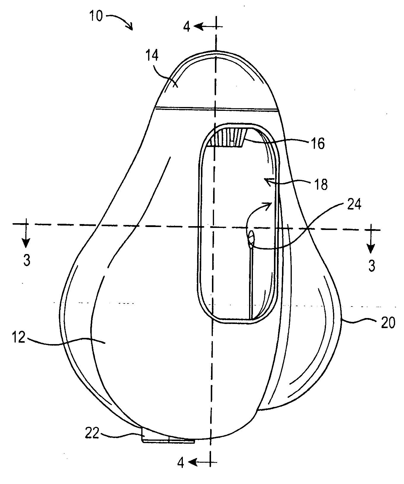
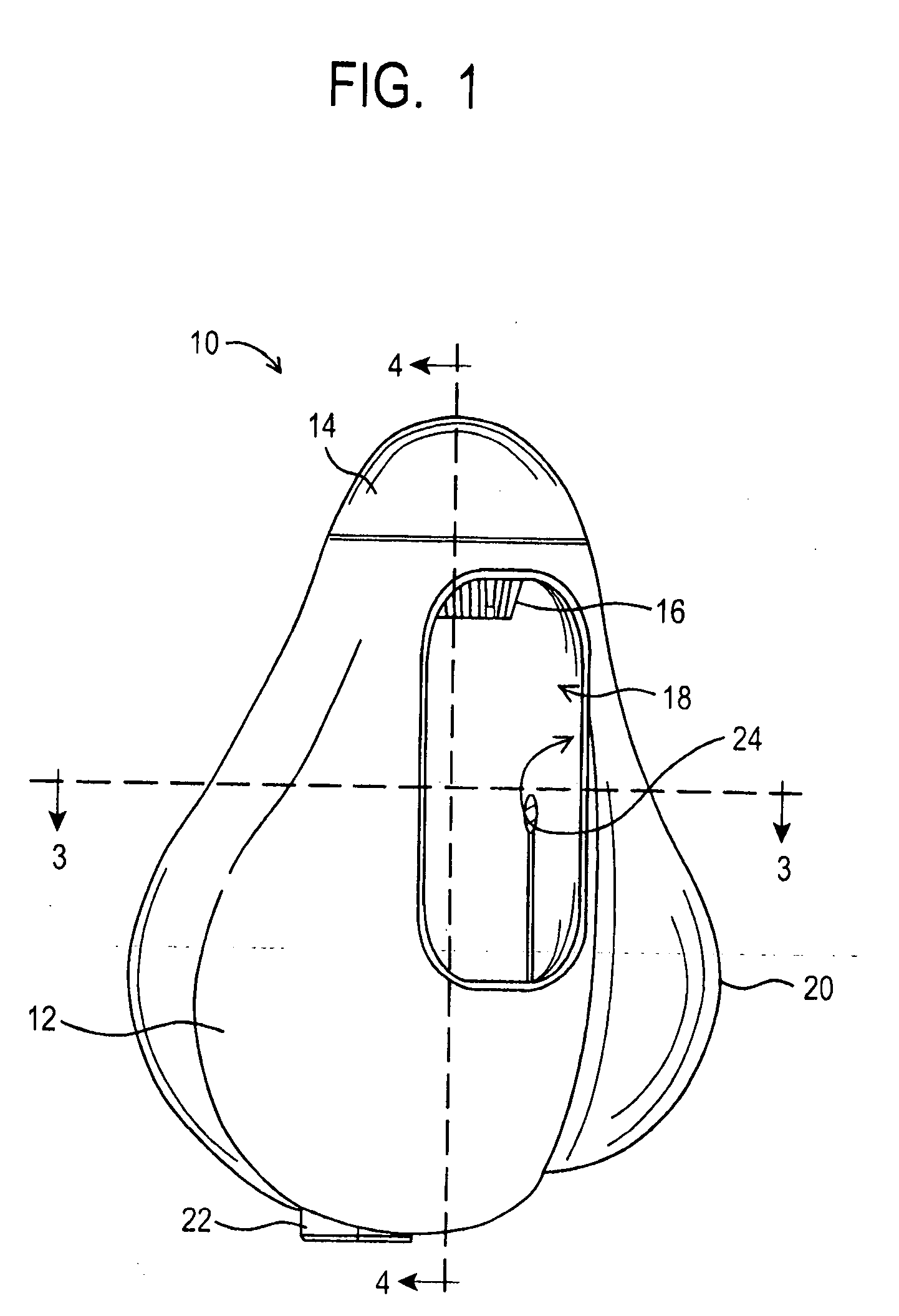
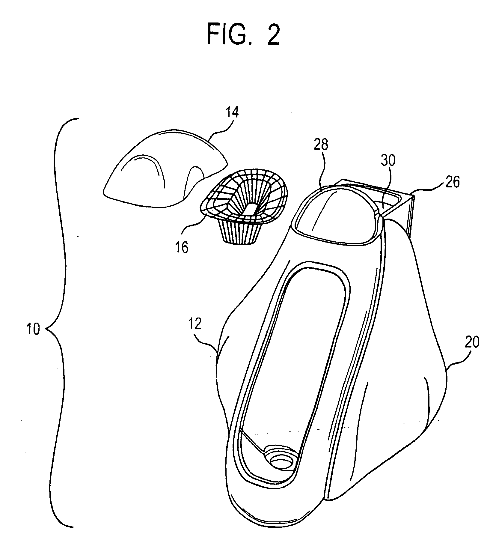
[0023] The present invention provides a wall or floor mounted urinal designed to minimize or eliminate splashback, while maximizing containment and disposing of substantially all liquid, vapors and gases that enter into the urinal and / or are created within the urinal. And, unlike conventional urinals, the urinal of the present invention may be customized in terms of exterior aesthetic form, including, but not limited to form, color, texture and patterns.

[0024] Referring first to FIGS. 1-4, the anti-splashback urinal 10 in accordance with the present invention comprises a bowl 12, having an opening 18 for receiving urine. The bowl 12 includes an inner surface 24 which has a curvilinear shape designed to reduce the angle of impact of urine flow from the user i.e. from the perpendicular, so that when urine is streamed against the inner surface 24, the urine is directed inward and downward, away from the opening 18. Reducing the angle of impact reduces both splashback and vaporization....


PUM


Abstract

An anti-splashback urinal, comprising a bowl for receiving a user's urine, the bowl having a surface with a curvilinear shape designed to reduce the angle of impact between the urine and the surface and to carry the urine down and away from a user; an aperture, through which the user deposits the urine into the bowl, the aperture being off-center with respect to the bowl; and a drain that is offset aligned from the aperture. The urinal may also include a custom outer cover having a shape and color/pattern to complement the room. In a preferred embodiment of the invention, the urinal is equipped with a low flow flush system having an armature that dispenses water at a low flow rate. The armature preferably comprises a plumbing tubing bent into a shape complementary to said urinal, and equipped with misting nozzles. In a particular embodiment, the urinal further comprises an air filter, which optionally may be a water stripper, connected to an air exhaust system, wherein air from the urinal enters the air exhaust system through the air filter, and wherein the air exhaust system is connected to a fan.

Description

REFERENCE TO RELATED APPLICATION [0001] This application claims priority from U.S. Provisional Applications Ser. No. 60 / 756,117, filed Jan. 3, 2006, and Ser. No. 60 / 793,689, filed Apr. 19, 2006.BACKGROUND OF THE INVENTION [0002] This invention relates generally to urinals and more particularly to wall and / or floor mounted urinals designed to minimize splashback, odor and water consumption. The invention also relates to urinals having custom covers having a shape and color / pattern to complement the room. [0003] Mens' restrooms typically contain wall and / or floor mounted urinals. These urinals provide convenient access for male patrons to urinate. Additionally, these urinals save space and reduce the amount of water otherwise used by water closets. [0004] A common problem with conventional urinals is the phenomenon known as splashback. Splashback occurs when droplets of urine are deflected back at the user due to the force of the user's stream of urine hitting a surface of the urinal....

Claims


Application Information

Patent Timeline
Patent Type & Authority Applications(United States)
IPC IPC(8): E03D13/00
CPCE03D5/10E03D13/00E03D9/052E03D9/05
Inventor BROWN, CHAD
Owner BROWN CHAD
Why Eureka
Try Eureka