Connector for a faucet

a technology for connecting pipes and faucets, applied in water installations, construction, domestic plumbing, etc., can solve problems such as poor utility of conventional connectors, and achieve the effect of reducing manufacturing costs and simplifying manufacturing processes

Inactive Publication Date: 2007-07-05
HORNG LAI IND CO LTD
View PDF2 Cites 20 Cited by
  • Summary
  • Abstract
  • Description
  • Claims
  • Application Information

AI Technical Summary

Benefits of technology

[0009] The main objective of the present invention is to provide a connector for a faucet, wherein the co

Problems solved by technology

Therefore, the conventional

Method used


Image

  • Connector for a faucet
  • Connector for a faucet
  • Connector for a faucet

Examples


Embodiment Construction

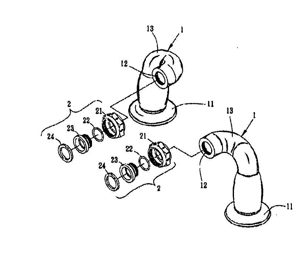
[0023] A connector for a faucet in accordance with the present invention is substantially a curved tube in one piece. The curved tube has two ends and a twist section and further comprises a mounting base and a coupler assembly respectively attached to the two ends of the curved tube. Selectively, the twist section extends between the two ends and is smoothly swirled and bent to make the curved tube non-planar in curving direction. Thereby, the connector has a simple structure and neat appearance to reduce manufacturing cost and to increase aesthetic appreciation. Moreover, the connector directly attaches the faucet to a wash basin in a convenient way and has no leakage problem itself because the connector is one-piece without any junction seam.

[0024] With reference to FIGS. 3 and 4, a preferred embodiment of the connector for a faucet is a curved tube 1 in one piece, wherein two connectors are attached between the faucet 3 and a wash base (not shown) or a proper object. Each curve...


PUM


Abstract

A connector for a faucet is particularly a curved tube in one piece. The curved tube has two ends and a twist section and further comprises a mounting base and a coupler assembly respectively attached to the two ends of the curved tube. Selectively, the twist section extends between the two ends and is smoothly swirled and bent to make the curved tube non-planar in curving direction. Thereby, the connector has a simple structure and neat appearance to reduce manufacturing cost and to increase aesthetic appreciation. Moreover, the connector directly attaches the faucet to a wash basin in a convenient way and has no leakage problem itself because the connector is one-piece without any junction seam.

Description

BACKGROUND OF THE INVENTION [0001] 1. Field of the Invention [0002] The present invention relates to a connector for a faucet, and more particularly to a connector that conveniently attaches the faucet to a wash basin and has a low manufacturing cost and a simple and graceful appearance. [0003] 2. Description of Related Art [0004] With reference to FIGS. 1 and 2, a faucet 30 is mounted on a wash basin (not shown) by connecting two conventional connectors. Each conventional connector between the faucet 30 and the wash basin comprises a first tube 10 and a second tube 20. The first tube 10 has a locking base 101 at one end to mount on the wash basin and a coupler 102 attached at the other end to connect to the second tube 20. The second tube 20 is perpendicularly attached to the first tube 10 and has a threaded flange 201 formed at a side near one end to engage the coupler 102 on the fist tube 10. Moreover, the second tube 20 operationally has a coupler 202 attached to a side near the...

Claims


Application Information

Patent Timeline
IPC IPC(8): E03C1/04
CPCE03C1/0403
Inventor SHIEH, MING-DANG
Owner HORNG LAI IND CO LTD
Why Eureka
Try Eureka