Heat shield having locating and retention features

Active Publication Date: 2007-07-05
FEDERAL MOGUL WORLD WIDE LLC
View PDF10 Cites 14 Cited by
  • Summary
  • Abstract
  • Description
  • Claims
  • Application Information

AI Technical Summary

Benefits of technology

[0008] The invention further contemplates a method of mounting a heat shield assembly to a member to be shielded that includes preparing the heat shield assembly having a channel-shaped shroud of heat shielding material with a pair of spring arms provided on side walls thereof and having at least one retention tab projecting into the channel, and then attaching the heat shield assembly to the member by extending the member into the longitudinal channel in a direction transverse to a longitudinal direction of the heat shield to engage the spring arms with the member thereby securing the shield ag

Problems solved by technology

Certain components of the engine are prone to generating significant heat, such as the exhaust manifold and associated exhaust piping system, the engine block, etc.
The excessive heat can be harmful to some neighboring components if left unprotected.
Such spring clips have limita

Method used


Image

  • Heat shield having locating and retention features
  • Heat shield having locating and retention features
  • Heat shield having locating and retention features

Examples


Embodiment Construction

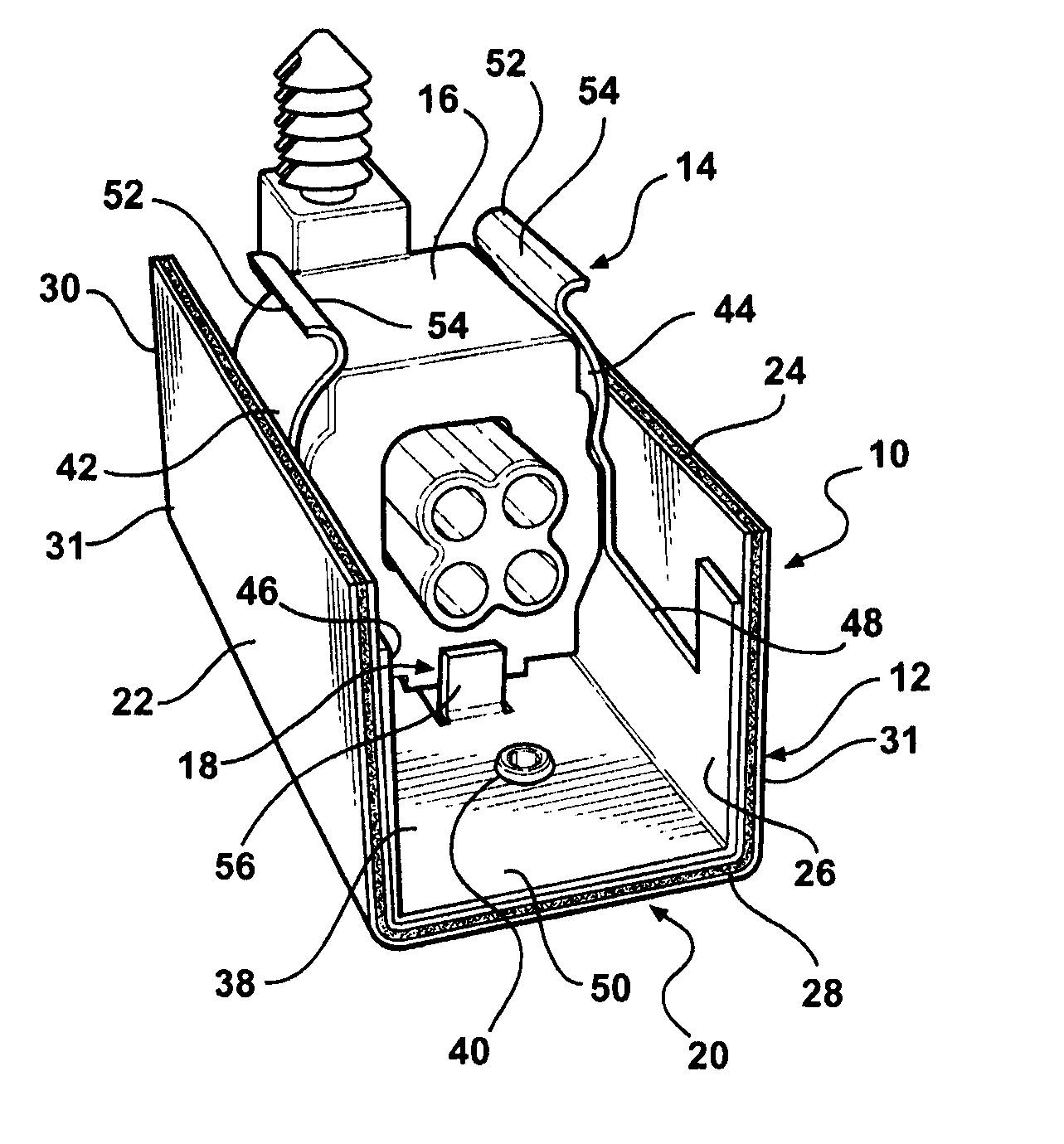
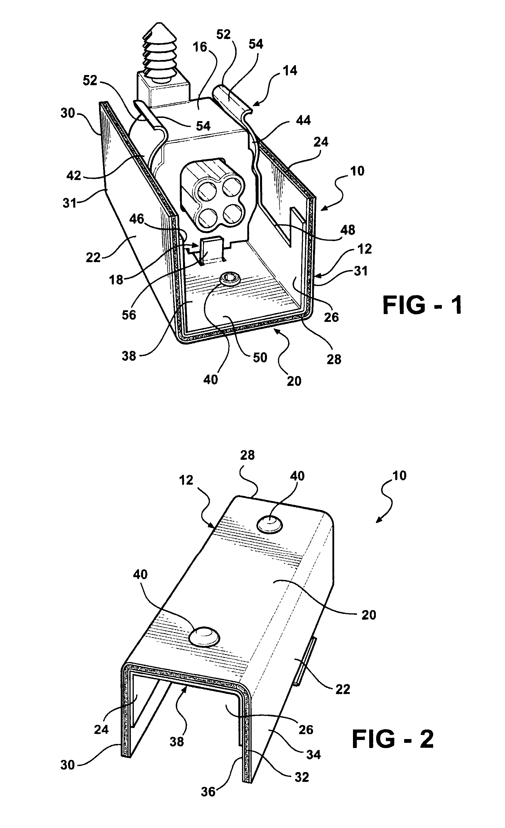
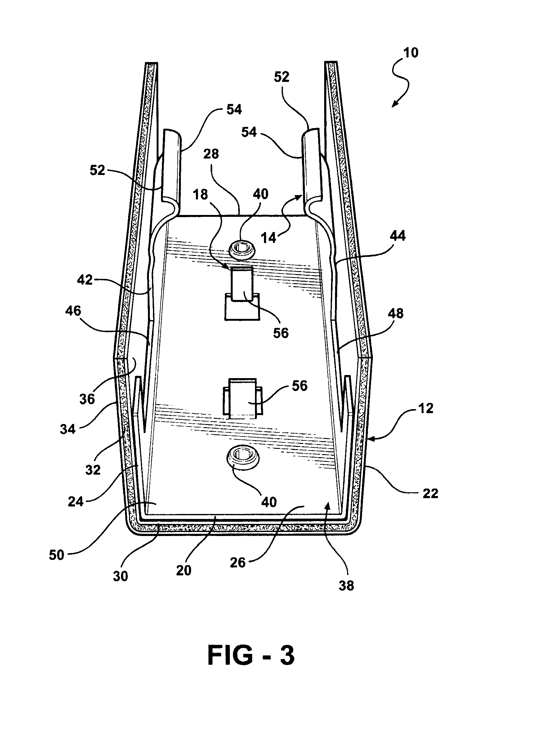
[0014] Referring to FIGS. 1 and 2, a heat shield assembly 10 according to a presently preferred embodiment of the invention includes a heat shield body or shroud 12, an attachment device 14 carried on the shroud 12 and operative for releasably securing the heat shield assembly to a member 16 to be protected by the heat shield assembly 10, and supplemental retention members 18 carried on the body in spaced relation to the attachment device 14 and operative to locate and selectively engage the member 16 to position and retain the heat shield assembly 10 on the member 16 in cooperation with the attachment device 14.

[0015] The shroud 12 may include a base 20 and at least two sides 22, 24. The sides 22, 24 extend from the base 20 in spaced apart relation to one another to define a space 26 into which the member 16 can be disposed for shielding the member 16 from exposure to heat external to the heat shield assembly 10. The heat shield assembly 10 is thus operative to cover and protect t...


PUM


Abstract

A heat shield assembly includes shroud or housing fabricated from a heat shielding material having at least one pair of spring arms extending from side walls of the shroud for engaging a member to which the heat shield assembly is to be attached, and one or more retention tabs projecting into a longitudinal channel in position to limit longitudinal movement of the assembly relative to the member when the member is attached to the spring arms

Description

[0001] This application claims priority to U.S. Provisional Application No. 60 / 756,521, filed Jan. 5, 2006.BACKGROUND OF THE INVENTION [0002] 1. Field of the Invention [0003] The invention relates generally to heat shields and more particularly to systems and methods for attaching heat shields to a member to be shielded. [0004] 2. Description of Related Art [0005] Engines in high performance modern vehicles operate at very high temperatures. Certain components of the engine are prone to generating significant heat, such as the exhaust manifold and associated exhaust piping system, the engine block, etc. The excessive heat can be harmful to some neighboring components if left unprotected. It is common to employ various heat shields in under-the-hood applications as a means of shielding such neighboring components from direct exposure to the damaging heat. Various techniques are employed for attaching the heat shield in a desired position to be effective. One such approach employs spr...

Claims


Application Information

Patent Timeline
IPC IPC(8): F02M35/02F01N13/14
CPCB60R13/0869F01N13/14F01N13/148Y10T29/49826F01N2560/00F01N2560/02F02B77/11F01N2260/20
Inventor UPTON, KENNETHBURDY, JOHN
Owner FEDERAL MOGUL WORLD WIDE LLC
Why Eureka
Try Eureka