Structure of antenna connector

a technology of antenna connectors and antenna connectors, which is applied in the direction of antenna connectors, coupling device details, coupling device connections, etc., can solve the problems of high error rate, inapplicability of abovementioned methods of fabricating antenna connectors, and time-consuming assembly by hand, so as to achieve effective promotion of fabrication yield and reliability of antenna connectors.

Inactive Publication Date: 2007-07-05
T CONN PRECISION CORP
View PDF3 Cites 5 Cited by
  • Summary
  • Abstract
  • Description
  • Claims
  • Application Information

AI Technical Summary

Benefits of technology

[0005] Accordingly, the present invention is directed to securely clip the cable the antenna connector such that the cable does not easily come loose. Thus, the fabrication yield and the reliability of the antenna connector can be effectively promoted.
[0006] According to an aspect of the present invention, the assembly of the metal plate, the isolation member and the cable may be carried out on an automatic workstation so as to eliminate time consuming and laborious manual assembly process may be effectively eliminated. Thus, the fabrication yield, the fabrication throughput and the reliability of the antenna connector may be effectively promoted.

Problems solved by technology

However, because the size of the connector is small and therefore assembly by hand is not only time consuming but also the error rate is high, such as electrical connection of the coaxial cable to the terminals may not be secure enough or the coaxial cable may be properly secured to the housing and may come loose.
Therefore, the abovementioned method of fabricating the antenna connector is not practical.

Method used


Image

  • Structure of antenna connector
  • Structure of antenna connector
  • Structure of antenna connector

Examples


Embodiment Construction

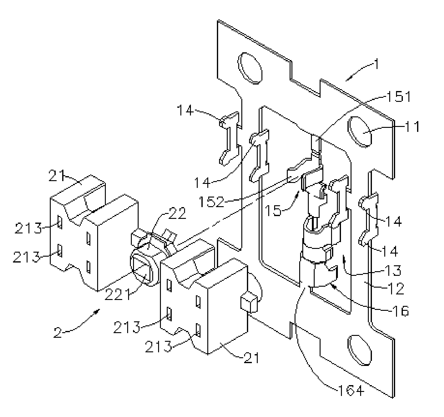
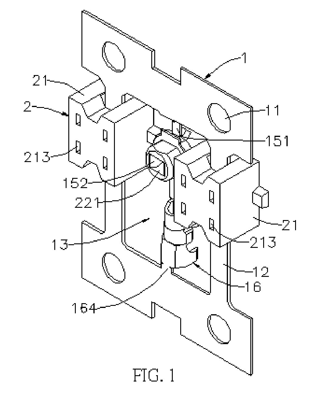
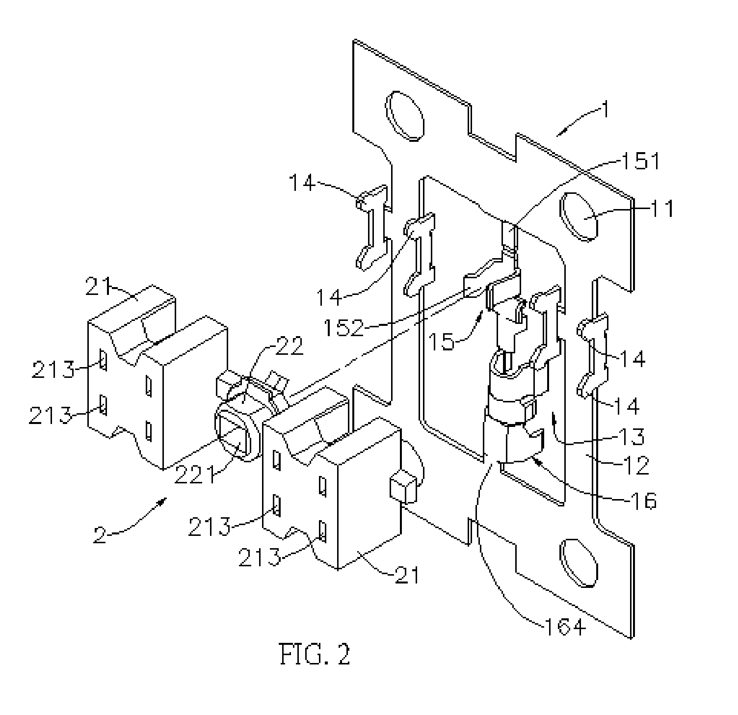
[0013] Referring to FIGS. 1˜4, the structure of an antenna connector comprises a metal tape 1 and an isolation member 2. The metal plate 1 and the isolation member 2 may be securely assembled together such that they cannot be easily disengaged from each other. Thus, the fabrication yield, the fabrication throughput and the reliability of the antenna connector may be effectively promoted.

[0014] The metal plate comprises a plurality of holes 11, two partitions 12, a terminal 15, two wing boards 14, clamp 16 and openings 13. The holes 11 are disposed on the peripheral region of the metal plate 1 and the partitions 12 define the openings 13. The two wing boards 14 extend via the connecting part 141 of the partitions 12. The terminal 15 is located between the two wing boards 14. The terminal 15 comprises a contact part 152 and a fastening part 153 connected to the contacted part 152. The contacted part 152 and the fastening part 153 are disposed opposed to each other. A clamp 16 is loca...


PUM


Abstract

A structure of an antenna connector is provided. The antenna connector comprises a metal plate and an isolation member. The metal plate comprises at least a terminal, two wing boards and a clamp, wherein the terminal is located between the two wing boards and the clamp is located below the terminal. The isolation member comprises a sleeve located at a position corresponding to the terminal of the metal plate and two fixing portions located at positions corresponding to the two wing boards. The two fixing portions comprise a plurality of slots for fixing the wind boards. To assemble the isolation member to the metal plate, the isolation member is placed over the metal plate such that the terminal is received within the sleeve of the isolation member and the two wing boards are fixed into the slots of the two fixing portions respectively.

Description

[0001] This application claims the priority benefit of a Taiwan patent application No. 094223200 filed on Dec. 30, 2005. FIELD OF THE INVENTION [0002] The present invention generally relates to a structure of an antenna connector, and more particularly to a structure of antenna connector, wherein the metal plate and the isolation member may be assembled by a simple assembly process and the cable may be securely fixed to the antenna connector so as to not to easily come loose from the antenna connector. The fabrication yield and the reliability of the antenna connector may be effectively promoted. DESCRIPTION OF RELATED ART [0003] Assembly of a conventional antenna connector is usually accomplished manually, wherein the terminals are assembled on an insulated housing by hand, and then a metal housing is covered on the insulated housing is covered by hand. Finally, a coaxial line is inserted through one end of metal housing by hand, and then the coaxial line is electrically connected ...

Claims


Application Information

Patent Timeline
Patent Type & Authority Applications(United States)
IPC IPC(8): H01Q1/50
CPCH01R2201/02H01R13/582
Inventor WONG, HSI-CHUAN
Owner T CONN PRECISION CORP
Why Eureka
Try Eureka